16
3. Fig. B: Place installation kit loosely onto frame of vehicle
and cross strut, with the exception of the stoppers (C – stop-
pers are attached when installation is complete).
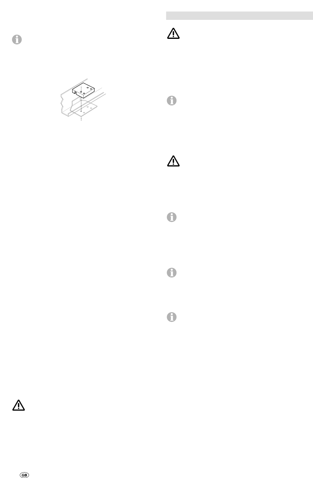
For chassis with U-profile frame, use U-profile frame kit
(Art. no. 60010-09200) instead of clamping plates provid-
ed for standard installation. Fit the two clamping plates to the
frame as shown in the illustration and attach using the U-bolts
and nuts provided in the installation kit. (The provided stoppers
replace the standard stoppers (C) and are attached when
installation is complete).
Position drive rollers such that they are in front of or behind the
tyres at wheel hub height (middle of wheel). No height com-
pensation is required for the standard installation (frame height
approx.185 mm).
With frame heights of 140 mm to 185 mm, use U-bolt exten-
sion kit (Art. no. 60010-00100) and spacer plate set (Art. no.
60010-65000) to set the drive rollers to the correct height
(middle of wheel).
For height compensation (as shown in fig. B) clamp 1 to 3
spacer plates (d) between the cross strut and the vehicle frame
(maximum of 3 plates). Use the extended U-bolts for installa-
tion.
For greater height differences, a flat frame kit (Art. no. 60010-
09400) is available from Truma as a special accessory – for
installation see instructions provided with flat frame kit.
In Germany, this flat frame kit installation must be accepted by
a vehicle expert.
4. Fig. C: Create an adequate distance between the chain
guard and the wheels/shock absorbers by moving the drive
units to the side so that they do not come into contact with
each other.
5. Fig. D: Move adjustable middle tube into a central position
and tighten the 2 bolts at the side a little.
Create the correct distance between the tyre and the roller
(20 mm) with the provided spacer by moving the drive units in
the longitudinal direction.
6. Once the drive units have been correctly positioned, tighten
the U-bolt nuts a little and then check that the distance be-
tween the rollers and the tyres is 20 mm. The weight of the
caravan must be on the wheels when doing this. Check that
there is adequate floor clearance.
7. Re-check the distance of 20 mm from the tyres (with weight
on wheels) and then tighten the nuts on the U-bolts (20 Nm for
W/F 13 mm), and the 4 bolts of the middle tube (15 Nm).
8. Fig. B: After installing in the correct position, fit stoppers (C)
immediately in front of and behind the retaining plates. The
stoppers prevent the Mover from sliding on the vehicle frame
during operation.
When the rollers are applied the minimum distance for
dimensions „a” and „b” is 10 mm (fig. C).
9. Once the Mover has been correctly fitted and secured, the
one-sided operating facility that is available as a special acces-
sory can be installed as described in the provided installation
instructions.
Installation of motor cables and control unit
Remove battery cable terminals and disconnect any ex-
ternal electrical power before starting work. If you are
unsure about the electrical installation, have it checked out by
a qualified Auto Electrician.
Pre-fitted, each motor has two heavy-duty cables (6 mm
2
). All
the cables have to be routed along the underside of the cara-
van floor to the point where the electronic control unit will be
situated. An example of a suitable location for the relay con-
troller is in a bed stowage box in close proximity to the ma-
noeuvring aid, at least 40 cm away from the battery.
The battery connection cables may not be lengthened.
The connecting cables to the motor and the battery must
be separate and must not be routed via the relay box.
1. Fig. F: Attach relay controller (installed horizontally with
antenna in a vertical position) to floor of stowage box with
provided screws.
2. Drill a 25 mm hole, approximately 150 mm in front of control
unit for the motor cables.
Take care to avoid any chassis members, gas pipes and
electrical wires)! The connecting cables to the motor and
the battery must not be routed parallel to each other.
3. Route motor connecting cable to relay controller along un-
derbody of caravan and attach to chassis or underbody using
the provided clips and screws. Take care to secure the cables
so they will not chafe on the chassis or sag below the floor
(use supplied protection tubing).
The motors move when the drive rollers are engaged,
so allow a little slack at the motors to avoid the cables
being stretched.
4. Mark the relevant motor connecting cables and then cut to
length accordingly (before or after the axle, depending on the
installation). Crimp provided spade connectors to the cables
(fig. G) and connect in accordance with wiring diagram
(fig. E) (red = positive, black = negative).
Excess cable must be cut to length and not looped inside
the bedding locker. A good quality connection on each
cable is essential!
5. Fig. E and F: Route battery connecting cables (10 mm
2
) to
relay controller and securely attach using the provided clips
and screws.
Route battery connecting cables so that they do not
chafe (particularly at leadthroughs through metal panels).
Use water hoses or leadthrough grommets to prevent damage
to cables. Connect battery connecting cables to the existing
battery terminals (red = positive, black = negative).
6. Re-check whether all cables are correctly connected,
attached using the provided clips and cannot chafe.