Einbau
Hinweis:
• Um Kurzschlüsse im elektrischen Systen zu verhindern, ist
unbedingt vor dem Einbau das Minus-Batteriekabel ·
abzutrennen.
• Bevor das Gerät endgültig montiert wird, die Kabel
provisorisch anschließen, und sicherstellen, daß alle Kabel
richtig angeschlossen sind, und Gerät sowie das System
richtig funktionieren.
• Um richtige Montage zu gewährleisten, nur die mit dem
Gerät mitgelieferten Teile verwenden. Durch den Gebrauch
von nicht zugelassenen Teilen können Funktionsstörungen
verursacht werden.
• Setzen Sie sich mit einem Händler in Ihrer Nähe in
Verbindung, wenn die Montage Bohren von Löchern oder
andere Modifikationen am Fahrzeug erfordert.
• Das Gerät so montieren, daß es den Fahrer nicht behindern
und im Falle einer Notbremsung den Beifahrer nicht
verletzen kann.
• Das Gerät nicht in der Nähe eines Warmluftauslasses, wo es
durch Wärme beeinträchtigt werden könnte, oder in der
Nähe der Türen montieren, wo es bei Regen Feuchtigkeit
ausgesetzt sein könnte.
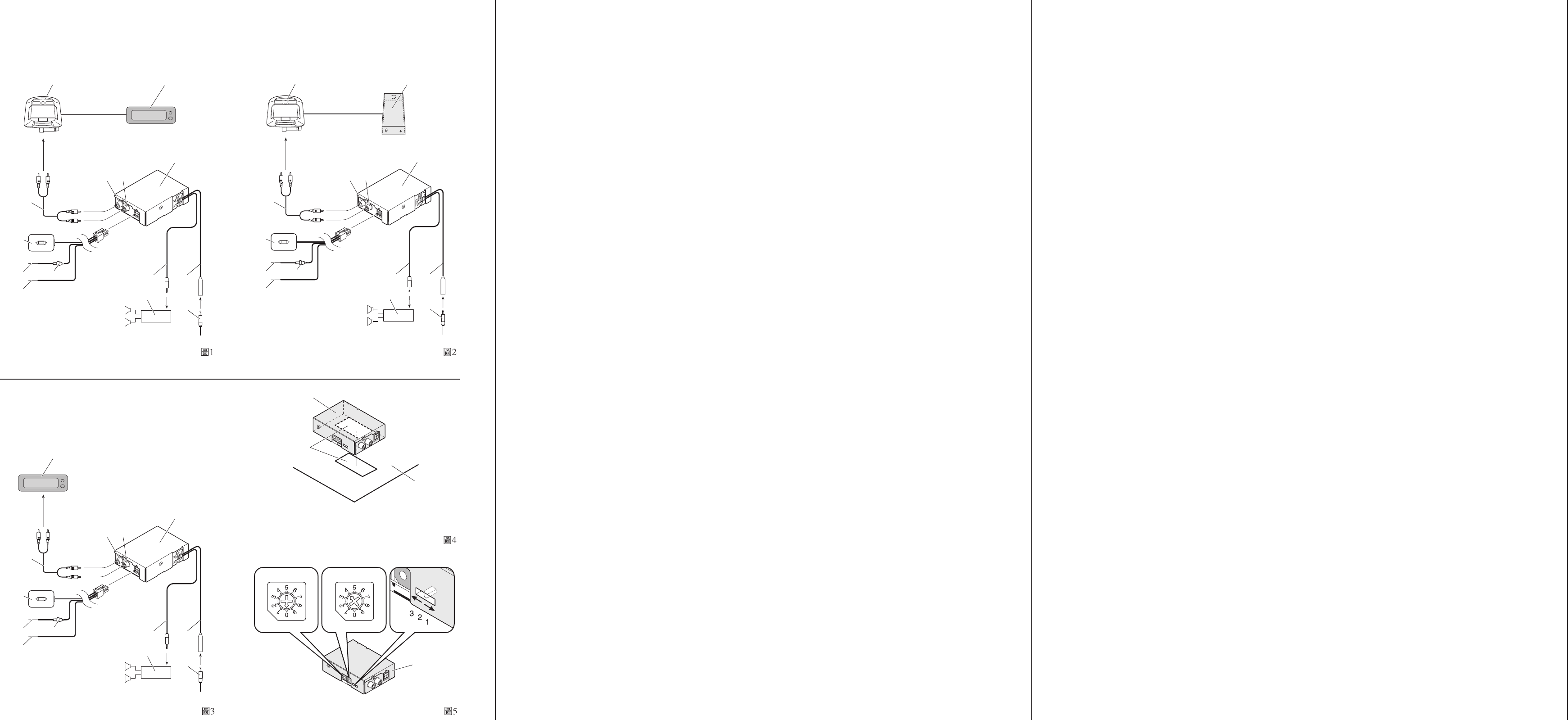
Einbau des Geräts (Abb. 4)
* Klettband
( Bodenmatte
• Klettband an der Unterseite des Geräts und an der
Bodenmatte des Fahrzeugs anbringen.
• Zum Anbringen von Klettband an der Einheit dieses entlang
der Seite des Antennenein-/ausgangs an der Unterseite der
Einheit, wie in der Abbildung gezeigt, so anhaften, daß das
Typenschild nicht überdeckt wird.
Technische Daten
Stromversorgung .................................... 14,4 V Gleichspannung
(Toleranz 10,8 – 15,1 V)
Max. Leistungsaufnahme .................................................. 200 mA
Gewicht ....................................................................................220 g
Abmessungen ................................... 89 (B) × 25 (H) × 64 (T) mm
UKW-Modulator-Nutzfrequenz ....... 88,1/88,3/88,5/88,7/88,9/89,1
/89,3/89,5/89,7/89,9 MHz
Hinweis:
Änderungen der technischen Daten und des Designs jederzeit
vorbehalten.
• Falls dieses Gerät unter einem Vordersitz montiert wird,
sicherstellen, daß der Sitz nach wie vor voll verschoben
werden kann. Alle Kabel sorgfältig um den
Verschiebemechanismus verlegen, so daß sie sich nicht
verfangen oder eingeklemmt werden können, um
Kurzschlüsse zu vermeiden.
• Wählen Sie für den Ein/Aus-Schalter eine gut zugängliche
Montagestelle im Fahrzeug. Bringen Sie ihn mit
doppelseitigem Klebeband auf seiner Rückseite an, nachdem
Sie zuerst Feuchtigkeit und Schmutz vollständig von der
Montagefläche beseitigt haben.
Vornehmen von Einstellungen (Abb. 5)
) Frequenzdrehschalter
• Sie können die von Ihrem Autoradio empfangene UKW-
Frequenz umschalten. Stellen Sie eine Frequenz ein, die von
keinem UKW-Rundfunksender in Ihrem Gebiet belegt ist. Im
Falle von Störungen drehen Sie den Schalter mit einem
Schlitzschraubendreher oder einem anderen geeigneten
Gegenstand nach rechts oder links, um eine andere
Frequenz zu wählen.
⁄ Modulatorpegel-Drehschalter
• Sie können den Lautstärkepegel einstellen. Vor dem Verkauf
wurde der Schalter auf 4 eingestellt. Falls Ihnen die
Lautstärke für Empfang von UKW-Programmen mit Ihrem
Autoradio zu niedrig ist, drehen Sie den Schalter mit einem
Schlitzschraubendreher oder einem anderen geeigneten
Gegenstand nach rechts. Wenn Ihnen die Lautstärke zu hoch
ist, bzw. wenn Verzerrungen auftreten, drehen Sie den
Schalter nach links. Je höher die Einstellnummer, desto
höher die Lautstärke.
¤ Preemphasis-Wähler
• Normalerweise wird der Preemphasis-Wähler auf “2”
eingestellt. (Die Ausgangseinstellung ist “2”.)
• Wenn Ihnen die Höhen zu schwach vorkommen, stellen Sie
den Wähler mit der Spitze eines Kugelschreibers oder eines
anderen spitzen Gegenstands auf “3”, um die Höhen etwas
zu betonen.
• Wenn die Höhen zu stark sind, und Klangverzerrungen
auftreten, stellen Sie den Wähler entweder auf “2” zurück
oder stellen Sie ihn auf “1” ein.
Instalación
Nota:
• Para evitar cortocircuitos en el sistema eléctrico, asegúrese
de desconectar el cable de la batería · antes de comenzar
con la instalación.
• Antes de finalizar la instalación de la unidad, conecte el
cableado temporariamente, asegurándose de que todo se
encuentra conectado apropiadamente, y la unidad y el
sistema funcionan apropiadamente.
• Utilice solamente las partes incluídas con la unidad para
asegurar una instalación adecuada. El uso de partes no
autorizadas puede ocasionar fallas de funcionamiento.
• Si la instalación requiere del taladrado de orificios u otras
modificaciones del vehículo, consulte con su agente o
concesionario más cercano a su domicilio.
• Instale la unidad en donde no interfiera con el conductor y
no pueda lesionar al pasajero en caso de una parada
repentina, tal como una frenada de emergencia.
• No monte esta unidad cerca de la salida del calefactor, en
donde podría ser afectado por el calor o cerca de las
puertas, en donde la lluvia podría salpicar sobre la misma.
Instalación de la unidad (Fig. 4)
* Cinta adherente
( Alfombra
• Fije la cinta adherente a la parte inferior de la unidad y a la
alfombra del vehículo.
• Cuando file la cinta adherente a la unidad, fije la cinta
adherente a lo largo del lado de la entrada/salida de antena
en el fondo de unidad como se muestra en la figura, de
modo que no cubra la placa de identificación en el fondo de
la unidad.
• Si esta unidad se instale bajo un asiento delantero,
cerciórese de que no obstruye el movimiento del asiento.
Pase todos los cables y conductores cuidadosamente a
través de los mecanismo deslizantes, de modo que no
queden aprisionados o atrapados en el mecanismo y
ocasionen un corto circuito.
Especificaciones
Fuente de alimentación ..... 14,4 V CC (10,8 – 15,1 V permisible)
Consumo de energía máximo .......................................... 200 mA
Peso ........................................................................................ 220 g
Dimensiones ................................. 89 (An) × 25 (Al) × 64 (Pr) mm
Frecuencia utilizable del modulador de FM
........................................................... 88,1/88,3/88,5/88,7/88,9/89,1
/89,3/89,5/89,7/89,9 MHz
Nota:
Las especificaciones y el diseño están sujetos a posibles
modificaciones sin previo aviso debido a mejoramientos.
• Fije el interruptor de alimentación en un lugar que se pueda
alcanzar fácilmente en el vehículo con la cinta de lado doble
en la parte posterior del interruptor de alimentación después
de limpiar completamente cualquier humedad y suciedad de
la superficie en la cual se fijará el interruptor.
Ajustes (Fig. 5)
) Interruptor giratorio de cambio de la frecuencia
• Se puede cambiar la frecuencia de la banda FM recibida por
su radio de automóvil. Ajuste a una frecuencia que no se
usa por ninguna emisora de radio FM en su área. Se hubiera
interferencia, utilice un destornillador u otro instrumento
para girar el interruptor hacia la derecha o izquierda para
seleccionar otra frecuencia.
⁄ Interruptor giratorio de nivel del modulador
• Se puede ajustar el nivel del volumen. Al comprar el
producto, el interruptor está ajustado a 4. Si siente que el
nivel del volumen está muy bajo para escuchar a las
emisoras FM en su radio de automóvil, utilice un
destornillador u otro instrumento para girar el interruptor
hacia la derecha. Si siente que el nivel del volumen está
muy alto o hay distorsión, gire el interruptor hacia la
izquierda. Cuanto más alto el número de ajuste, más alto
será el nivel del volumen.
¤Selector de preamplificación
• Normalmente, ajuste el selector de preamplificación a “2”.
(El ajuste inicial es “2”.)
• Si siente que los agudos están insuficientes, cambie el
selector a “3” con la punta de un bolígrafo u otro
instrumento puntiagudo para acentuar los agudos
ligeramente.
• Si siente que los agudos están muy fuertes y el sonido se
pone distorsionado, retorne el selector a “2” o cámbielo a
“1”.
Making adjustments (Fig. 5)
) Frequency switching rotary switch
• You can switch the FM band frequency received by your car
radio. Set it to a frequency that is not used by an FM radio
broadcast station in your area. If there is interference, use a
standard tip screwdriver or other instrument to turn the
switch clockwise or counterclockwise to select another
frequency.
⁄ Modulator level rotary switch
• You can adjust volume level. At the time of purchase, the
switch is set to 4. If you think the volume level is too low to
listen to FM broadcasts on your car radio, use a standard tip
screwdriver or other instrument to turn the switch clockwise.
If you think the volume level is too high or there is
distortion, turn the switch counterclockwise. The higher the
setting number, the higher the volume level.
¤ Pre-emphasis selector
• Normally, set the pre-emphasis selector to “2”. (The initial
setting is “2”.)
• If you feel the treble is insufficient, switch the selector to “3”
with the tip of a pen or other pointed instrument to boost
the treble slightly.
• If you feel the treble is too strong and the sound becomes
distorted, either return the selector to “2” or switch it to “1”.
Installation
Note:
• To avoid shorts in the electrical system, be sure to
disconnect the · battery cable before beginning installation.
• Before finally installing the unit, connect the wiring
temporarily, making sure it is all connected up properly, and
the unit and the system work properly.
• Use only the parts included with the unit to ensure proper
installation. The use of unauthorized parts can cause
malfunctions.
• Consult with your nearest dealer if installation requires the
drilling of holes or other modifications of the vehicle.
• Install the unit where it does not get in the driver’s way and
cannot injure the passenger if there is a sudden stop, like an
emergency stop.
• Do not mount this unit near the heater outlet, where it would
be affected by heat, or near the doors, where rainwater
might splash onto it.
Installing the Unit (Fig. 4)
* Velcro tape
( Floor mat
• Attach Velcro tape to the bottom of the unit and the floor
mat of the vehicle.
• When attaching the Velcro tape to the unit, affix the Velcro
tape along the side of the antenna input/output on the
bottom of the unit as shown in the figure so that it does not
cover the name plate on the bottom of the unit.
• If this unit is installed under a front seat, make sure it does
not obstruct seat movement. Route all leads and cords
carefully around the sliding mechanism so they do not get
caught or pinched in the mechanism and cause a short
circuit.
• Attach the power switch at a location that can be easily
reached in the vehicle with the double-sided tape on the
back of the power switch after first completely wiping off
any moisture and dirt from the surface on which it is to be
attached.
Specifications
Power source ....................... 14.4 V DC (10.8 – 15.1 V allowable)
Max. current consumption ............................................... 200 mA
Weight .................................................................................... 220 g
Dimensions ...................................... 89 (W) × 25 (H) × 64 (D) mm
FM modulator usable frequency .... 88.1/88.3/88.5/88.7/88.9/89.1
/89.3/89.5/89.7/89.9 MHz
Note:
Specifications and the design are subject to possible
modification without notice due to improvements.
Fig. 1, Abb. 1, Afb. 1, Fig. 2, Abb. 2, Afb. 2,
Fig. 3, Abb. 3, Afb. 3,
Fig. 4, Abb. 4, Afb. 4,
Fig. 5, Abb. 5, Afb. 5,