Client Invensys File 7406 Dr
Ar -
Pro
PRINT
Finished Siz A3 297x420mm
Creative Direc Mik Ar 100%
Modification Da 18/05/1 Bleed 3mm
1.
ID Fe Description: Factor
5 BACKLIGHT Ava TIM
6 OFFSE Ad 0.0°
7 LOC Pro
T
T
000
Ma
8 CTRL-TY Co
9 CTRL Se TPI
CYCL-R
or
Se 6 cp
HY Sel
re
0.
MI Se 5 min
DONE T
10 V Th
th
OFF
11 WIRELESS T Pre-
12 BIND Pre (
) key to s
NB
BINDING An R
If u
13 SIG In
VERY
DONE T
15 PROD- V(
) key to s
16 RESET Wi OFF
DONE E
I Guide
S Signal Strengt
Th
MiS
to b
co
Signal strength indicator
se
It i
or V
maintain
T (see s
•
I
• pr(
) to enter
• Pre
• pr( ) to
• pr
• pr( ) to se
St Mounting Opt S Ins
On
sh
shown.
Customize the
NB
st
C
po
draughts
wa
it c
dir
of
S Moun St Wir
! IMP
In
qualifi
Ma
! CAUTION!
ma
Option 2
Lo
an
cl
ab
pro
ne
su
wa
Ch
Option 1
Th
he
in an o
me
ho
mo
th
fr
Lo
an
th
wa
te
wa
or o
us
cl
ab
wa
in s
Pla
the secur
Ch
Warning: Ins
me
wi
Applications
The electronic room
for temperature
• Boilers
• Oi
• Ac
• Circulat
• Heat p
A MiS
Note: T
sy
hav
he
Note:T
th
ac
Th
! DO N
us
mounting bo
This product is double
do
Th
boiler or
co
R sh
room or
as s
diagrams.
Always check other
instr
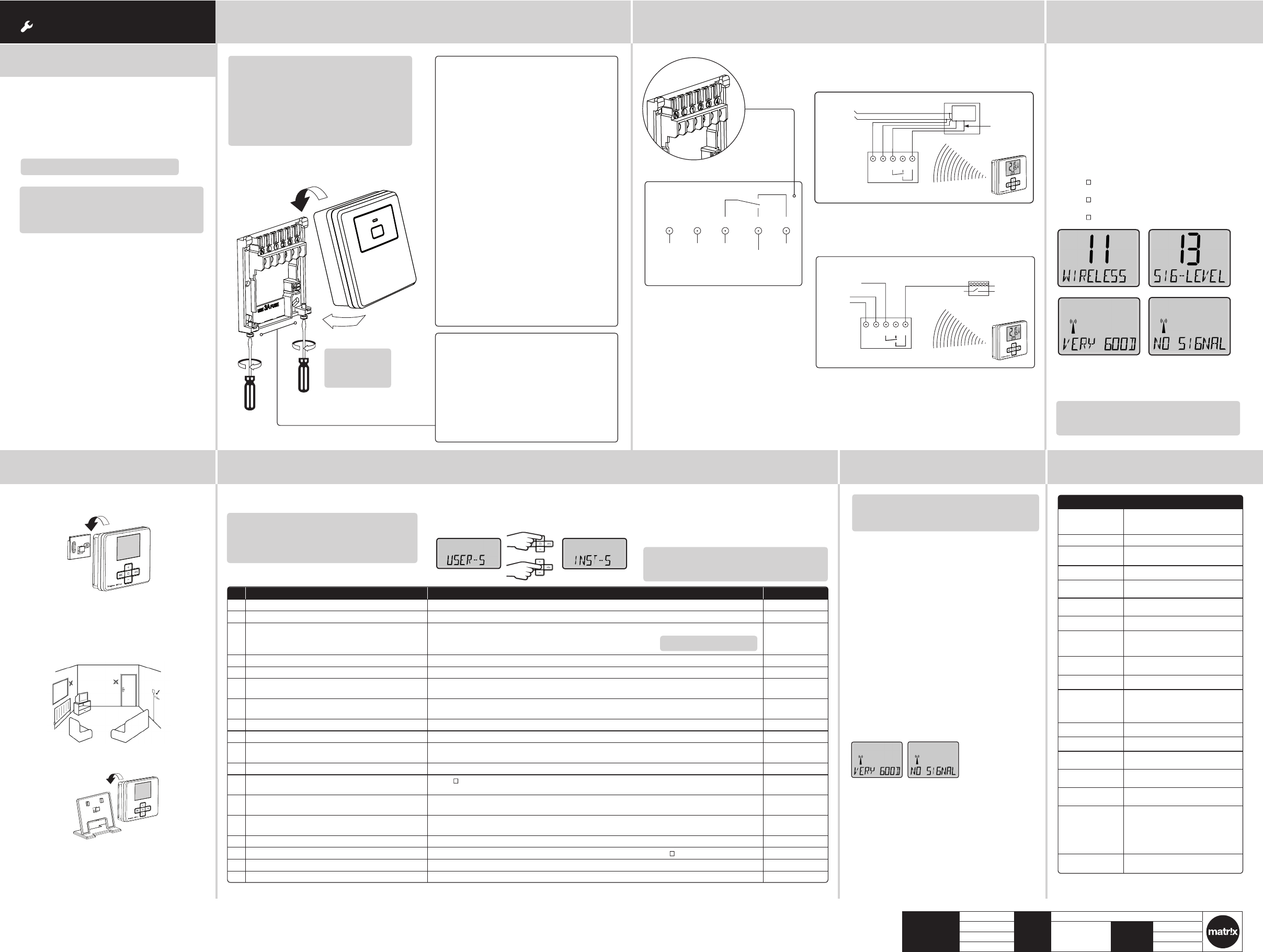
N L 1 2 3
230V AC 50Hz
Fused 3A
Common
heating
satisfied
or call for
cooling
Call for
heat
Volt free contacts
Comb
Zone control basic wiring la
Note: If no
For commissioning
Note: Onl
replacing
MiStat receiv
T
Pre
pr
is n
me
1. T
co
alr
(If a s
th
2. Pus
fl
3. Enter bindi
MiS
i
Impor It i
carr
uni
4. If b
be i
th
FAIL
is d
SI
th
Mi
MiStat R
Immediately af
the signal qualit
• thr
• dou
• sin
• s
T
A gre
connec
T
Pre+ & – key
se
Note: If no
For commisioni
T
St C
Mi
Supply voltage Mi
bat
Mi
Switch rating Mi
Ambient
temperature
Op
Sto
Batte MiSt
T
range
5°C t
T
resolution
0.
Control accuracy <0.6°C a
Wiring Mi
wi
Mi
Mounting Mi
Mi
Radio frequency 868.3 (Bi-direc
Radio signa 30
af
an
MiStatN and
Pollution 2
Soft A
Rated impu
voltage
Mi
Ball pressure
temperature
Mi
Energy Class IV = 2
812
Releva
Directives:
20
2004/1
Compat
1
2006/66/EC
201
Applied
Standards:
EN
E
eg. eg.
eg. eg.
User Code:
N L 1 2 3
L
MiStat R
MiStat R
Switched live
from wiring
centre
Motorised valve
N
To boiler
and/or
pump
Radio signals
to MiStat R - no wiring
230V AC
fused 3A
N L 1 2 3
L -
N -
Radio signals
to MiStat R - no wiring
Switched
230V AC
fused 3A,
Internal
boiler
electronics
External
controls
connections
N L 1 2 3
L
MiStat R
MiStat R
Switched live
from wiring
centre
Motorised valve
N
To boiler
and/or
pump
Radio signals
to MiStat R - no wiring
230V AC
fused 3A
N L 1 2 3
L -
N -
Radio signals
to MiStat R - no wiring
Switched
230V AC
fused 3A,
Internal
boiler
electronics
External
controls
connections
If POOR is
If N
th
Ca
Th
el
en
wi
mu
In o
inst
Th
is d
an
el
operates according working principle
It h
control the room