In the top part of the surround, it is necessary to provide non closable convection air holes for a convection air output, inthe bottom part, there
is a need of convectional air input - minimal diameter depends on output of the fireplace insert, mentioned in the technical list. You need to
consider non effective parts of the grilles (20-40% of the grille area, depending on design also) when choosing the convenient grilles for
input/output of the convectional air and take into account also way of the using (in technical list, nominal output of the fireplace insert is
mentioned and the real output depends on the amount of wood in use, the real output can be for short period higher of 50%).
The minimal dimensions of the convectional air grilles for input and output are mentioned in the following chart:
Fireplace insert output (kW)
Convectional air input –grille dimension
(cm2)
Convectional air output –grille dimension
(cm2)
6-9
700
1000
10-15
850
1200
15-20
1100
1600
After the fireplace installation neither the air input nor the air vent can be restricted by building panels. We recommend
ordering a professional firm.
To prevent heat accumulation the holes for conventional air must be open during heating. No lockable grates, ribs, blinds, etc. can be installed into the
holes. In the top part the convection coating must be finishedby the partition wall above the hole, so as not to make a thermal pocket. (see Surround
diagram).
Convection cross-section between the insert and the coating as well as the insulation on the rear side –please check the chart with
measures of protection (see pict.06 )
Note: These minimal distances in accordance with the Equipment Certificate must be kept
to on all heights and widths of the fireplace insert so as to allow convection air to flow
through.
Convection air area:If a prefabricated area for convection air is not used (lining made of a galvanized sheet), it is necessary to maintain a
distance according to the chart on page n.6between the fireplace insert and rear thermal insulation layer.
The fireplace insert assembly: The fireplace insert can be placed on a fitted base after the making of the thermal insulation as in the
installation instructions. The fireplace insert is connected with the chimney by the connecting piece (smoke flue).
Extension joint:It is necessary to have an extension joint at least 3 mm thick between the insert and the coating. The extension joint can
be stemmed by a ropeor sealing tape.
Coating (fireplace surround):The coating of the fireplace insert which leads into the room must be made of non combustible material of
grade A1 (e.g. tiles, plaster coat, iron or ceramic tiles). There must not be any direct contact between the coatings and the fireplace insert.
The coating may overlap only on the separate carrying frame which is clamped to the wall. For adjustment, maintenance of a safety valve,
a pump and accessories or possible repairs it is necessary to provide the surround with service holes. These holes are necessary for these
operations and it is not needful to build the surround.
Ornamental beams: Ornamental beams are allowed in front of the fireplace coating at a distance of 1 cm at least if the ornamental beam is
not a part of the building and the intermediate space is such that it does not accumulate heat and the ornamental beam is notsituated
within the area of the insert heat radiation.
Fire protection in a heat radiation area
A minimum distance of 80 cm forwards and sideways must be retained in front of the firebox hole (pict.6, position 1). If the
protection against heat radiation is from both sides, a distance of 40 cm is enough (pic. 6, position 2).
frame
Part of
veneer
pict. 6
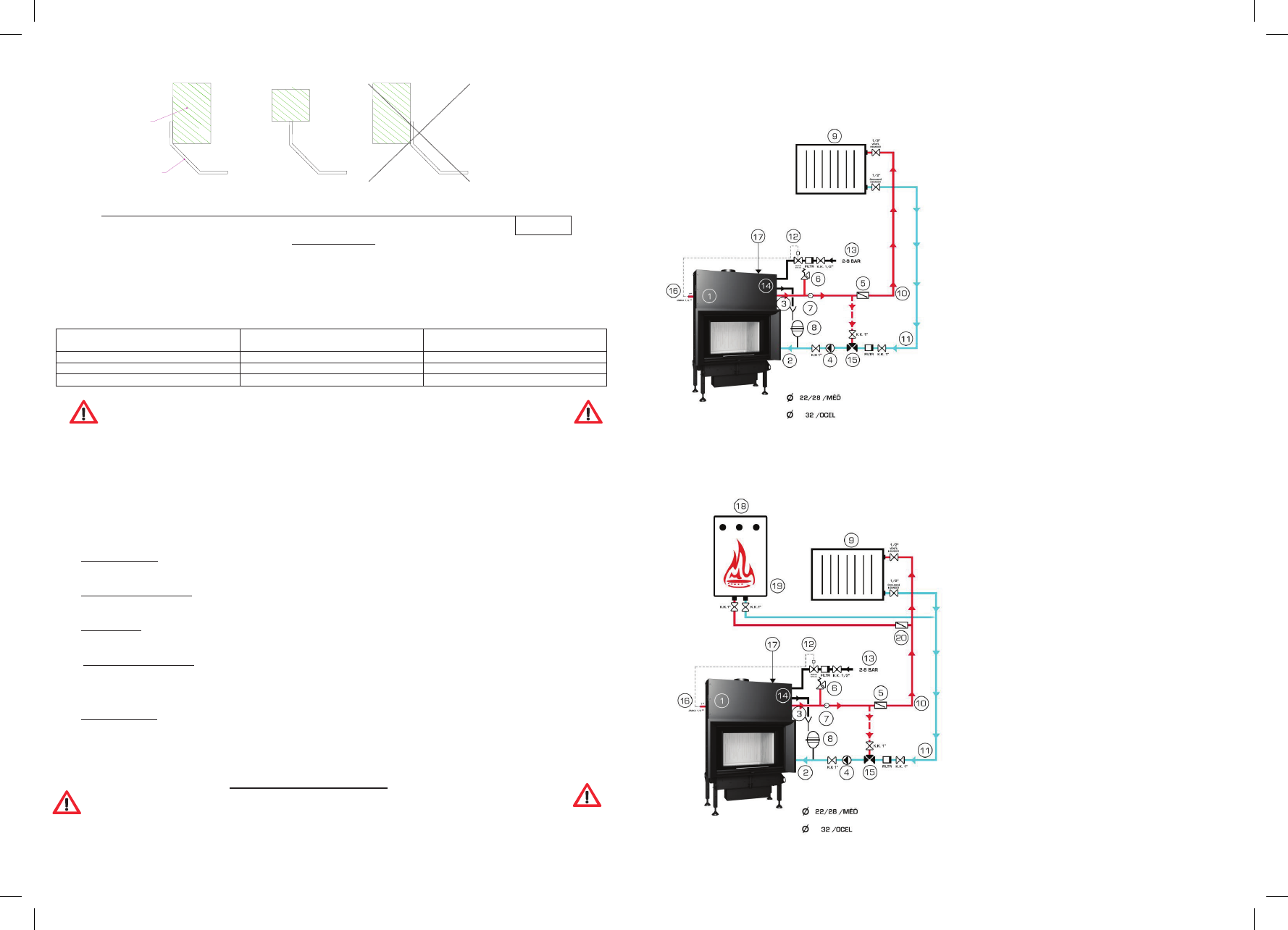
CONNECTION WITH THE CENTRAL HEATING SYSTEM
THE INSTALLATION OF THE FIREPLACE INSERT THE CENTRAL HEATING SYSTEM CAN BE REALIZED ONLY BY AN
EXPERT IN ACCORDANCE WITH NATIONAL STANDARDS AND THIS INSTALLATION MANUAL
Fireplace connection pict. 3
System of the central heating and the hot water fireplace insert
installation:
1.HOT WATER FIREPLACE INSERT
2.COLD WATER INLET DN 25 (BACKWARD)
3.WARM WATER OUTLET DN 25 (RISER)
4.CIRCULATING PUMP OF THE FIREPLACE
5.CLAP VALVE OF THE FIREPLACE
6.PRESSURE FELIEF VALVE 2,5 bar.
7.DISCHARGE PIPE OUTLET
8.OPEN EXPANSION BOX
9.SYSTEM OF RADIATORS
10.WARM WATER MAIN PIPE (RISER)
11.COLD WATER RETURN PIPE (BACKWARD)
12.THERMOSTATIC SAFETY VALVE
13.WATER SUPPLY CONNECTION
14.COOLANT LOOP
15.THERMOSTATIC MIXING VALVE
16.SENSOR OF A THERMOSTATIC VALVE
17.BLEED VALVE
Fireplace connection pict.4:
Central heating system with the hot water fireplace insert
Gebruikershandleiding.com neemt misbruik van zijn services uitermate serieus. U kunt hieronder aangeven waarom deze vraag ongepast is. Wij controleren de vraag en zonodig wordt deze verwijderd.
Product:
Spelregels forum
Om tot zinvolle vragen te komen hanteren wij de volgende spelregels:
lees eerst de handleiding door;
controleer of uw vraag al eerder door iemand anders is gesteld;
probeer uw vraag zo duidelijk mogelijk te stellen;
heeft u een probleem en al geprobeerd om dit op te lossen, vermeld dit erbij aub;
heeft u een oplossing gekregen van een bezoeker dan horen wij dat graag in dit forum;
wilt u een reactie geven op een vraag of antwoord, gebruik dan niet dit formulier maar klik op de knop 'reageer op deze vraag';
uw vraag wordt direct op de website gezet; vermijd daarom persoonlijke gegevens in te vullen;
Belangrijk! Als er een antwoord wordt gegeven op uw vraag, dan is het voor de gever van het antwoord nuttig om te weten als u er wel (of niet) mee geholpen bent! Wij vragen u dus ook te reageren op een antwoord.
Belangrijk! Antwoorden worden ook per e-mail naar abonnees gestuurd. Laat uw emailadres achter op deze site, zodat u op de hoogte blijft. U krijgt dan ook andere vragen en antwoorden te zien.
Abonneren
Abonneer u voor het ontvangen van emails voor uw BeF Home Bef Aqualie bij:
nieuwe vragen en antwoorden
nieuwe handleidingen
U ontvangt een email met instructies om u voor één of beide opties in te schrijven.
Ontvang uw handleiding per email
Vul uw emailadres in en ontvang de handleiding van BeF Home Bef Aqualie in de taal/talen: Engels als bijlage per email.
De handleiding is 1,86 mb groot.
U ontvangt de handleiding per email binnen enkele minuten. Als u geen email heeft ontvangen, dan heeft u waarschijnlijk een verkeerd emailadres ingevuld of is uw mailbox te vol. Daarnaast kan het zijn dat uw internetprovider een maximum heeft aan de grootte per email. Omdat hier een handleiding wordt meegestuurd, kan het voorkomen dat de email groter is dan toegestaan bij uw provider.
Uw handleiding is per email verstuurd. Controleer uw email
Als u niet binnen een kwartier uw email met handleiding ontvangen heeft, kan het zijn dat u een verkeerd emailadres heeft ingevuld of dat uw emailprovider een maximum grootte per email heeft ingesteld die kleiner is dan de grootte van de handleiding.
Er is een email naar u verstuurd om uw inschrijving definitief te maken.
Controleer uw email en volg de aanwijzingen op om uw inschrijving definitief te maken
U heeft geen emailadres opgegeven
Als u de handleiding per email wilt ontvangen, vul dan een geldig emailadres in.
Uw vraag is op deze pagina toegevoegd
Wilt u een email ontvangen bij een antwoord en/of nieuwe vragen? Vul dan hier uw emailadres in.