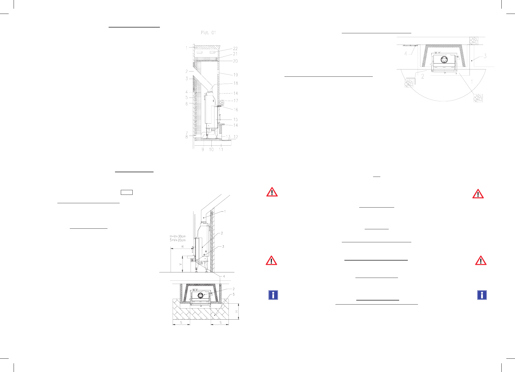
Fireplace insert location diagram
The hot water fireplace inserts in accordance with EN 13229
1.
Protected ceiling made of combustible materials or as a conductive element
2. Artificial construction material: heating protective measure in accordance with national technical
standards and regulations
3. Connecting pieces made of steel sheets
4. Thermal insulation layer: back wall, side wall, ceiling, convectional air chamber
5. Brick veneer
6. Protected wall made of combustible material or a conductive element made of concrete or iron
concrete
7. External combustion air input
8. Protecting grille
9. Thermal insulation layer
10. Conductive plate
11. Protected base plate made of non combustible material
12. Screening protection of the floor of non combustible material
13. Convection air input
14. Coating
15. Fireplace insert
16. Conductive frame
17. Ornamental beam
18. Butterfly valve d=200mm
19. Grill of air output
20. Conductive element (non combustible material)
21. Thermal insulation layer of 6 cm thickness
22. Interspaces’ ventilation
Ceiling (floor) protection
Ceilings without a sufficient lateral distribution (e.g. wooden ceilings) must be protected by a 6 cm thick concrete layer and 6 cm thick thermal
insulation layer where the fireplace insert is situated. Consulting a structural engineer is recommended. If the floor, where the fireplace insert will be
situated, has an adequate lateral distribution a 6 cm thick thermal insulation layer is enough.
pict. 02
The floors in front of the fireplace insert
A floor made of combustible material in front of the fireplace insert must be protected
by an adequate incombustible material layer. Dimensions of this incombustible area are
at least: 800mm in the sideways direction of the opening side and 400mm to the front in
the direction of the opening side.
The chimney connection
If the existing chimney is not provided with a suitable connecting fitting for the
fireplace insert it is necessary to make an additional connection. The chimney
connection height is arrived at the properly situated fireplace insert and an attached
smoke flue elbow and a connecting fitting – measured from the top edge of the support
plate to the centre of the connecting fitting in the entrance of the connecting area. Gaps
for the surround, insulation, expansion joint, etc. must be taken into account. pict. 02
1 – smoke flue
2 – fireplace insert
3 – bottom of the hearth
4 – surround
5 – floor
Before starting the unit for the first time it is necessary to let authorized
person do the inspection in accordance with national standards.
Fire protection above a heat radiation area
A minimum distance of 5 cm from the outer space of the insert coating to non-
combustible building panels must be retained. Air space must be clear so as not
to accumulate heat (pict. 6, position 3). Building panels covering only small
coated areas of the fireplace insert, e.g. floors, wall coating and thermal
insulation layers may abut onto the coating (pict. 6, position 4). Wider
combustible building panels, e.g. ornamental beams, may be at a distance of 1 cm
from the insert coating.
External air input for combustion into the fireplace insert
Hot water fireplace inserts are adjusted for direct connection for external
combustion air inflow. Bellmouth of diameter of 120 – 150 mm for external
combustion air connection is ending on the back side (or bottom side) of the
fireplace insert. Inflow for outdoor air connection for combustion in a fireplace
insert must have as few bends as possible. For air inflow within the distance of
1.5 m with one bend (max. 90°) it is possible to use a pipe of diameter 100 mm.
For air inflow within the distance of 3 m with one or two bends (total disjunction of angles 135°) it is possible to use a pipe of diameter 125 mm.
When there is longer distance and more bends, it is necessary to take into account air resistance caused by friction of tube walls.
It is possible to supply hot water fireplace inserts with automatic electronic regulation of the combustion process. Automatic regulation consists
of control unit, control damper and temperature sensor. Control dumper must be situated in supply pipes, as close as possible to fireplace insert
and connect hermetically onto bellmouth of the air inflow. After building of the fireplace, the dumper must be accessible for service. When
automatic regulation is in use, it is convenient to set up the hand-operated element in the 2/3 open position (providing right proportion of the air
for nominal output of the insert). Also, fireplace insert can be fitted with door contact for easy service (position of the door contact is described
below in paragraph “door adjusting and unhanging). More detailed description of connection and installing you will find in installing document
of Automatic regulation.
When automatic regulation is in use, manually operated element must not be closed!
Fireplaces with open hearth must be supervised all the time to prevent dangerous sparks and falling out wood pieces burning.
Fuel
Fireplace inserts can be operated only with the following fuel:
dry wooden logs
ONLY DRY WOOD LIBERATES LITTLE HARMFUL POLLUTANTS DURING BURNING!!!
A fireplace insert is not suitable for waste burning!!!
Combustion air input
It is necessary to supply a sufficient amount of external air into the room when using the fire. Both open and closed fireplaces require an
adequate amount of fresh air. The steps for combustion air input cannot be changed and combustion air inputs must be open during the working
operation of the firebox.
Convection air
To prevent heat accumulation, the incoming and outgoing grates of convection air must be open when using the fire.
Fire protection above a heat radiation area
A minimum distance of 5 cm from the outer space of the insert coating to non-combustible building panels must be retained
Fire protection in a heat radiation area
A minimum distance of 80 cm forwards and sideways must be retained in front of the firebox hole - (furniture, carpets,
plants etc.)
Protection against injuries
Do not forget that heaters have hot surfaces. Use the enclosed protective glove when working with the fire. You could be in a heat radiation area
(80 cm) only during mending, and if there is further contact, the skin can be burnt. Keep the fireplace out of the reach of children.
Application and activation
Acceptable fuel, economical and ecological operation:
The fireplace insert is designed to use wood as fuel. The water content is max. 20% of dry weight. Logs should be stored in a dry and well
ventilated place for two years. Using wet logs leads to smoke with a tar condensation which could damage the chimney. In any case there is
excessive environmental pollution. Logs should be 30 cm.
Wood is a very gaseous fuel and needs a lot of secondary air. Regulation with the help of slow or permanent burning is not possible with this
kind of fuel. Heating output during wood burning is determined by the amount of the fuel used.
The most ecological and economical is dry wood burning, because the heating quality of fresh wood is lower than that of dry wood.
As for burning waste, it must be stressed, that burning material such as plastic material, cardboard, painted wood, etc. are harmful for your
fireplace insert and furthermore is prohibited by the Emission Act. It is allowed to use firelighters, paper and small wood for lighting a fire only.