FAN-COIL 4T
Electronic Controller
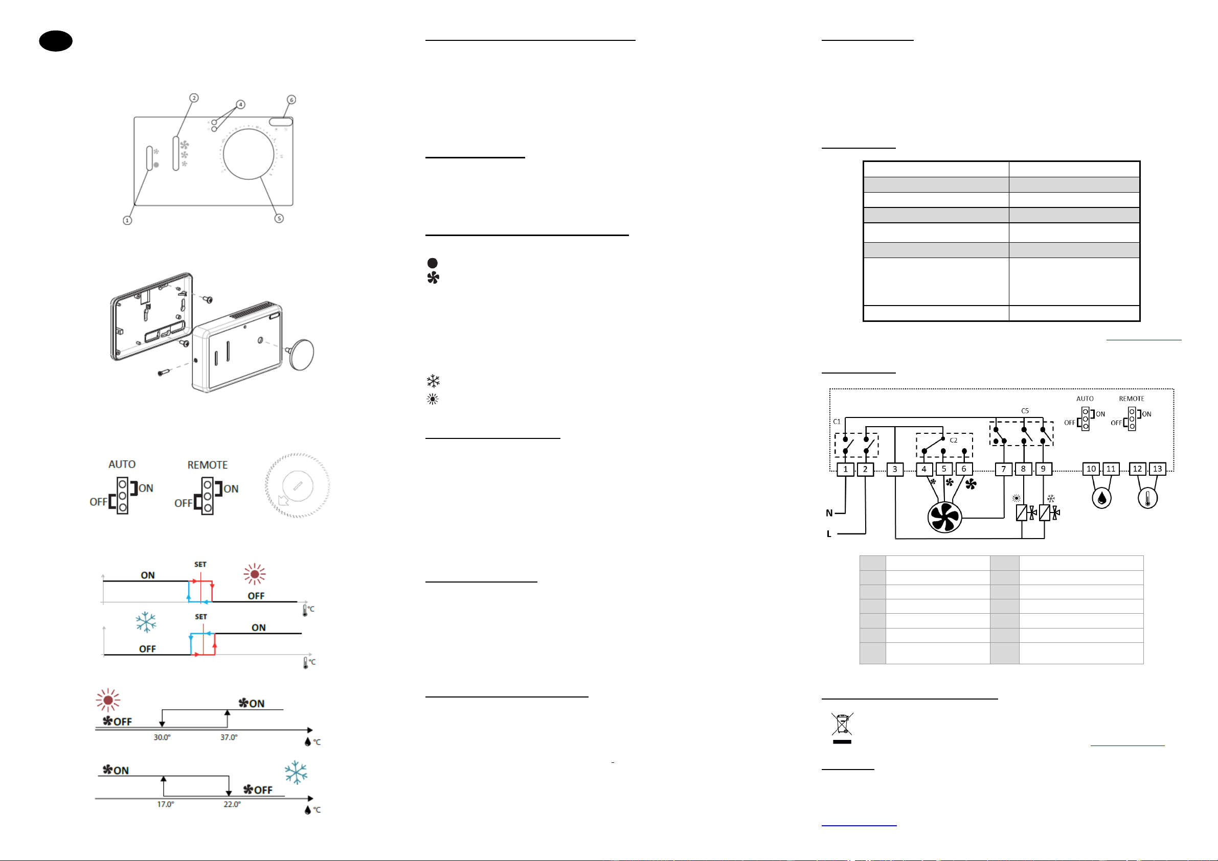
Fig. 1
Fig 2.
Fig.3
Fig.4
Fig 5.
Safety warnings and operating instructions
• This product should be installed preferably by a qualified professional. Subject to observation of the
above terms, the manufacturer shall assume the liability for the equipment as provided by legal
stipulations. All instructions in this
Installation & Operation manual should be observed when working with the controller.
• Failures due to improper installation, improper use or poor maintenance are voiding manufacturer
liability
• Any attempt to repair voids the responsibility and the obligation to guarantee and replacement from
the manufacturer.
Product description:
FAN-COIL CONTROLLER 4T: Fan-coils electronic controller suitable for models equipped with
double heat exchanger (4-pipes plants), 3-speeds asynchronous electric motor connected to the fan,
ON/OFF type valves, SUMMER/WINTER switch either manual or automatic (on the basis of the air
temperature), ventilation consent on the basis of the water temperature (if necessary).
Operating instructions and legend (Fig.1):
① – Two steps ON/OFF button
OFF mode
ON mode with manual ventilation
② – Manual ventilation switch (minimum, middle, maximum speed)
④ – Blue and red warning
Led is permanently blue: fan coil is in cooling mode
Led is permanently red: fan coil is in heating mode
Red led is blinking: water temperature is too low to heat
Both red and blue led blinking: temperature probe is faulty or disconnected
⑤ – Control knob for temperature setting from 5 to 35 °C
⑥ – Manual switch mode
SUMMER/COOLING
WINTER/HEATING
Wall mounting instructions:
Install the controller in an easily accessible area suitable for functions setting and efficient for room
temperature detection (at least 1.5 m from the floor). Therefore, avoid:
• direct sunlight exposure
• direct exposure to hot or cold air currents
• placing obstacles which impair correct temperature detection (curtains or furniture);
• the constant presence of water vapour (kitchens, etc.)
• covering or recessing the controller into the wall.
Please, respect the following instructions (Fig.2)
• remove the controller temperature setting knob
• remove the controller closing screw
• pass the cables through the slots on the base and fasten the controller with the reserved holes
• close the controller back up using the closing screw and insert again the temperature setting knob
Electrical connections:
All of the operations must be carried out by qualified staff, in accordance with regulations in force.
For any electrical related procedure, refer to the electrical diagrams attached to this documentation.
We also suggest making sure that the characteristics of the electrical network are suitable for the
absorption levels reported in the electrical data table. Before carrying out any operation on electrical
parts, make sure the power supply is disconnected. Check that the net voltage is compatible with the
specifications of the unit (voltage, number of phases, frequency) shown on the unit rating plate. The
supply voltage must not fluctuate by more than ±5% in relation to the rated value. The electrical
connections must be set up according to the electrical diagram attached to the specific unit and with
the regulations in force.
Operating and adjustment setting
On the electric circuit of the controller there are electric devices able to modify three different settings:
• REMOTE jumper used to specify the position of the air probe on the basis of which the
controller makes the adjustment. The two possibilities are on board probe (factory default
setting) or remote wired probe (Fig. 3).
• AUTO jumper to specify how the changeover (SUMMER/WINTER) is supposed to be applied
by the controller). The two possibilities are the manual selection (factory default setting) or the
automatic changeover on the basis of air temperature (Fig. 3).
• Potentiometer for the hysteresis calibration (from 1°C to 10°C) around the temperature SET
for the automatic SUMMER/WINTER changeover, we suggest not to modify this value if not
strictly necessary, for example as a consequence of a quick and large variation of the air
temperature (Fig. 3)
Adjustment logics:
The thermostat operation (either cooling or heating) takes place with a difference of 0,2°C from the
set point of the controller (Fig. 4). The thermostat switches on the fan and opens the valve (if any).
Ventilation is activated (limited to 2 minutes every 8 minutes) and forced without a real necessity only
with the following setting: cooling mode and remote air probe; this is due to the fact that in this
situation a good air temperature detection is possible only if the air is periodically moved.
The water consent to ventilation (only if the water probe is connected) is driven by the activation and
deactivation logic reported in figure 5.
Technical data: