
-
mijn vdo dayton heeft op beeldscherm geen beeld en hij staat op contact tevens heeft het geen nut om op de afstandsbediening te drukken, mijn beeldscherm heeft ook een aan/uit knop en deze reageert ook niet Gesteld op 21-5-2015 om 20:39
Reageer op deze vraag Misbruik melden-
Dit heb ik ook, is er een oplossing? Geantwoord op 30-9-2015 om 23:24
Waardeer dit antwoord (11) Misbruik melden
-
-
Ik ook. Heeft iemand een oplossing? Scherm blijf op AV2 staan Geantwoord op 28-10-2015 om 10:01
Waardeer dit antwoord (3) Misbruik melden -
als ik t contact van mn captiva draai komt mn scherm niet meer omhoog? weet iemand de oplossing? Gesteld op 13-8-2014 om 13:55
Reageer op deze vraag Misbruik melden-
HEBT U HIER EEN OPLOSSING VOOR GEVONDEN ? Geantwoord op 5-10-2015 om 14:44
Waardeer dit antwoord (10) Misbruik melden
-
-
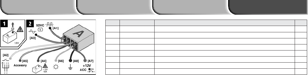
hai ik heb een vdo pc5100 overgenomen
Reageer op deze vraag Misbruik melden
heb alleen geen gebruiks aanwijzing om hem aan te sluiten
hoe kan ik hier aan komen
gr henk Gesteld op 30-1-2014 om 22:28-
Ook ik heb een pc5100/00, en ook geen handleiding, op deze site staat er ook niks over Geantwoord op 13-1-2016 om 13:29
Waardeer dit antwoord Misbruik melden
-