4
Installation of the
safety/drain valve
Fig. B + C: Install safety/drain
valve (13) at a place which is
easily accessible, near the
water heater. Drill hole with
18 mm diameter and pass
through discharge socket
with hose (14). Fasten safety/
drain valve with 2 screws.
The draining is to be directly
to the outside at a position
protected against splash wa-
ter (apply splash guard, if
necessary).
Water pipe routing
1. Fig. B + C: Connect cold
water supply (24) to safety/
drain valve (13). Direction of
flow is unimportant.
2. Fig. D: Screw elbow with
integrated breather valve (15)
to hot water connection pipe
(upper pipe) and elbow with-
out breather valve (16) to cold
water connecting pipe (lower
pipe).
Slide on nut (17), tension ring
(18) and O-ring (19). Assem-
ble screw connector and con-
necting pipe and fasten to-
gether using nut (17).
Slide ventilation hose with
11 mm outer diameter (20)
onto the breather valve hose
nozzle (21) and route towards
the outside. Do not allow the
radius of the arc to be less
than 40 mm.
Cut off the ventilation hose
approx. 20 mm below the
floor of the vehicle at an an-
gle of 45° to the direction of
travel.
3. Fig. B + C: Produce hose
connection (22) for cold wa-
ter supply between safety/-
drain valve (13) and elbow
(16 - lower pipe) on water
heater.
4. Route the hot water pipe
(23) from the elbow with inte-
grated breather valve (15 -
upper pipe) to the hot water
consumers.
4
Installation of the
control panels
Attention: When using con-
trol panels which are specific
to the vehicle or the manufac-
turer, the electrical connec-
tion must be established in
accordance with the Truma
interface descriptions (refer to
Electrical connection 230 V).
Any modification made to the
Truma components pertaining
to this will lead to the invali-
dation of the guarantee, as
well as to the exclusion of any
claims for liability. The installer
(manufacturer) is responsible
for providing instructions for
use for the user as well as for
identification printing on the
control panels.
When selecting the location,
bear in mind that the control
panels must not be subjected
to direct radiant heat. Length
of connection cables 2.5 m.
Control panel,
gas operation
If required, for the gas opera-
tion control panel a cable ex-
tension of 5 m can be sup-
plied (Art. No. 70000-53500).
1. Pass control panel cable
through the cable binder on
the back of control panel.
Connect cable to the control
panel and tighten cable
binder as strain relief.
Fasten control panel using
2 screws and route the cable
to the water heater.
Note: Depending on the in-
stallation, the routing of the
control panel cable can be
done in the other way. This
means first connect to the
water heater and then route
to the control panel.
Truma control panel,
electrical operation
Fig. E: When selecting the
place of location, always
make sure that the control
panel (27) is not exposed to
direct heat radiation.
Drill a hole with 8 mm diam-
eter for leading through the
cable and pass the cable
through the hole. Fasten con-
trol panel with the two
screws and route the cable to
the appliance.
5
Electrical
connection 12 V
Always disconnect the ap-
pliance from the power
supply prior to working on
electrical components. It is
not sufficient to just
switch off at the control
panel!
The appliance must be dis-
connected from the vehicle
main power supply when car-
rying out any electric welding
work on the vehicle body.
Attention: If the connec-
tions are transposed there
is a risk of cable burning.
This also rules out any
guarantee or liability
claims.
Fig F: Unscrew cover (34)
from the electronic control
unit. Slide cable connector of
control panel (28) onto the
p.c.b.. The electrical connec-
tion is made at terminal (35)
(red = positive, blue = nega-
tive), for this purpose press
with a small screwdriver from
above and push in cable from
the front. Connect to fused
vehicle mains (central electri-
cal equipment 5 - 10 A) using
a 2 x 1.5 mm
2
cable.
Negative cable to central
earth. With lengths of over
6 m use a cable 2 x 2.5 mm
2
.
If connecting directly to the
battery, the positive and neg-
ative cable must be fused.
Screw cover (34) back on.
There are to be no other con-
sumers connected to the sup-
ply line!
The water heater fuse,1.6 A
EN 60127-2-3 (slow-acting) is
on the p.c.b. (36).
When using power packs, ob-
serve that the appliance is on-
ly to be operated with safety
extra-low voltage according
to EN 60742!
Note: For the connection of
several 12 V appliances we
recommend the electronically
controlled Truma power pack
NT (Art. no. 39900-01). The
Truma power pack (6 A con-
tinuous current) is also suit-
able for charging lead batter-
ies. Other charging devices
are only to be used with a car
battery acting as buffer. Pow-
er packs and power supply
units must have a stabilised
12 V-output (ripple content
less than 1 Volt).
6
Electrical
connection 230 V
Attention: The electrical con-
nection is only to be carried
out by an expert (in Germany,
acc. to VDE 0100, Section
721). The information given
here is not intended as infor-
mation for the layman, rather
it is to for assisting the as-
signed expert, as additional
information, when connect-
ing the appliance!
The connection to the power
supply is by means of a cable
3 x 1.5 mm
2
(e.g. flexible
sheathed cable H05VV-F) to a
splitting box (not included in
scope of delivery).
Always pay attention to con-
nect carefully with the correct
colours!
For maintenance and repair
work a disconnecting device
must be provided on the vehi-
cle for all-pole disconnection
from the power supply, with
at least 3 mm contact clear-
ance.
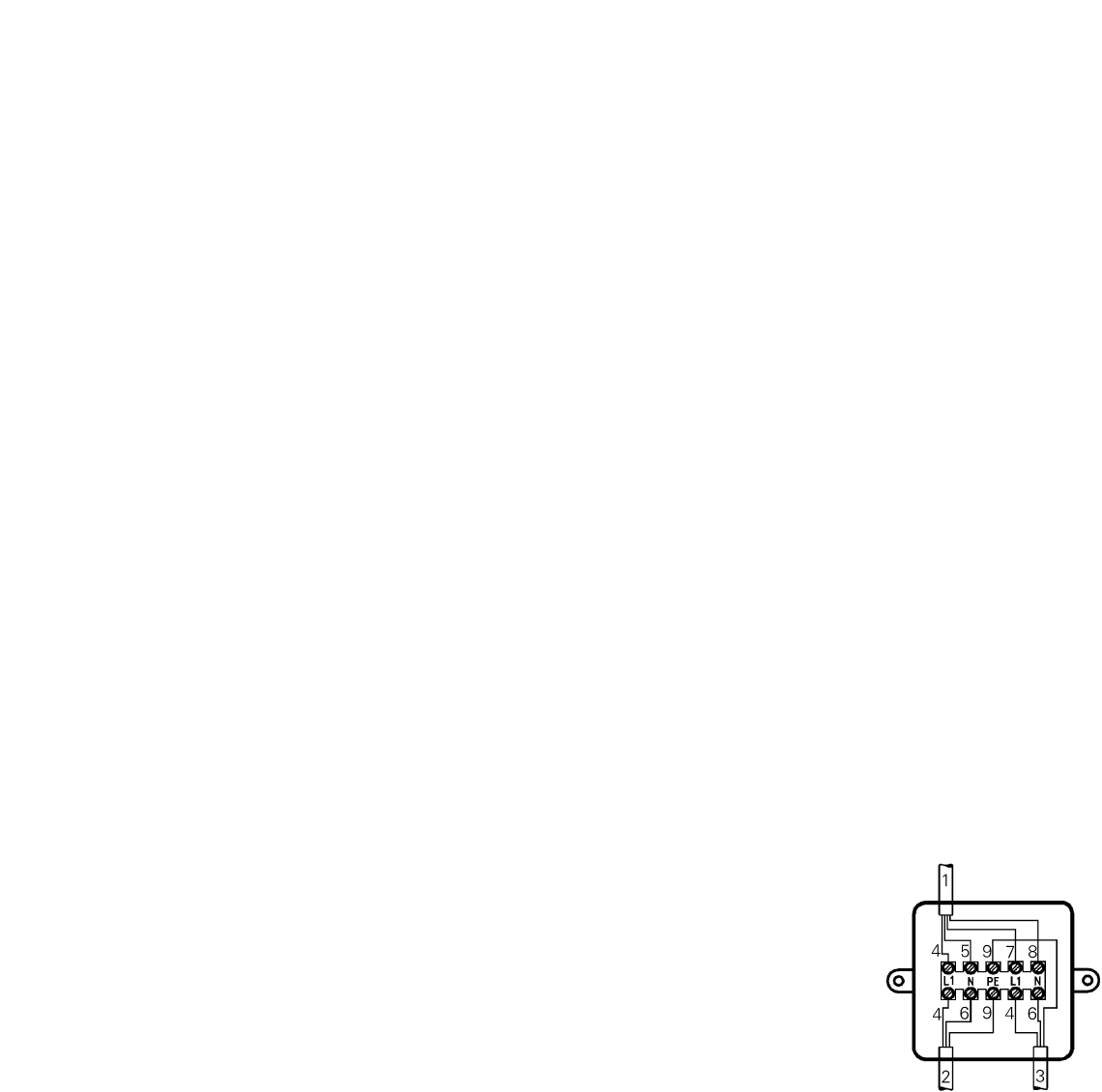
Connection 230 V with
Truma control panel
1. Connect control panel ca-
ble, supply line 230 V and
heating element cable as
shown in the drawing.
1 = Control panel cable
2 = Supply line 3 x 1,5 mm
2
3 = Heating element cable
4 = brown
5 = green
6 = blue
7 = yellow
8 = white
9 = yellow/green
2. Assemble the splitting box
(Fig. E: 37) on the vehicle
floor or on the wall, in the
vicinity of the appliance (ob-
serve cable length 150 cm!).
Note: All cables must be
secured with cable clips.