Dimmer outputs
LUXOR 405 (D1 and D2) 2 x 300 VA
D1 only 1 x 500 VA
Info:
• The outputs are adjacent and isolated for
the supply.
• Any external wire/phase can be connected!
• Semi-conductor switch outputs
Operating Manual
Dimmer module
LUXOR 405
1.0 Designated use
2.0 Brief description
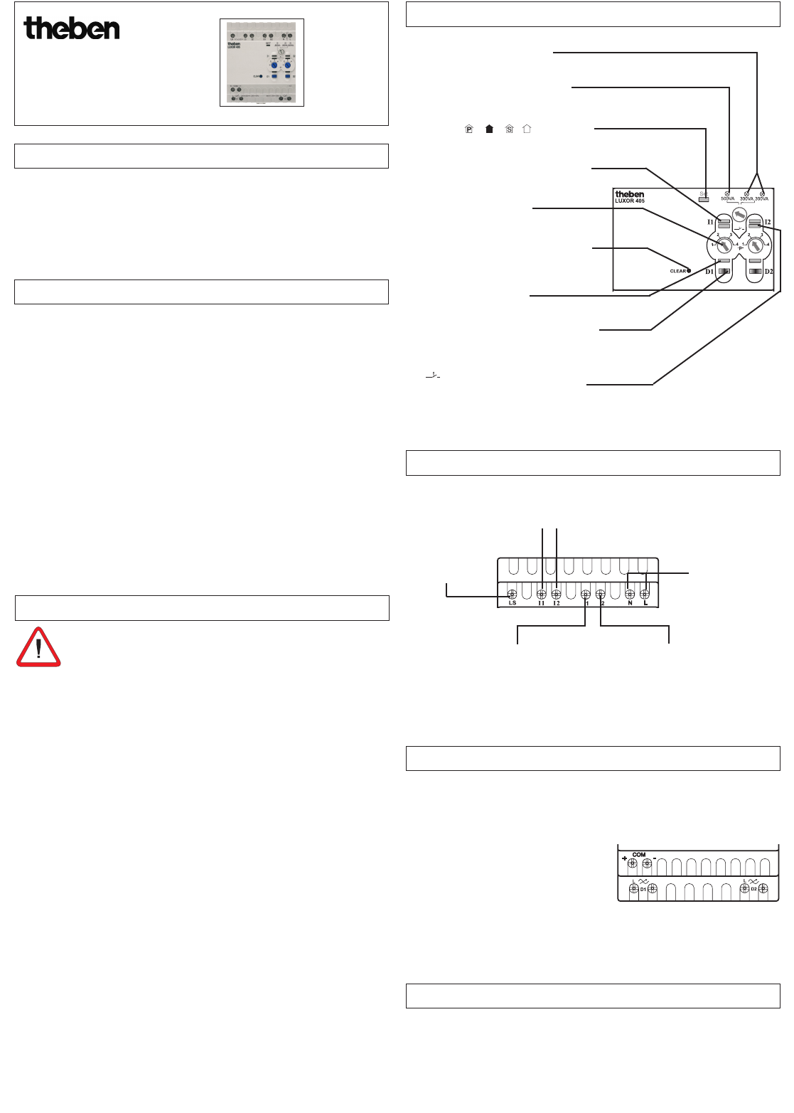
4.1 Description of input terminals
3.0. Safety notes
4.0 Description of control level
4.2 Description of output terminals
5.0 Connecting upgrade devices
LUXOR 405
The LUXOR dimmer module expands the existing LUXOR seriesof devices. It is
suitable for installation in single-family and multiple family houses, offices, etc.
The device is intended for designated installation in control and distribution
cabinets. It is suitable for use in dry rooms with a normal amount of dirt.
In order to eliminate danger of fire and danger of an electric shock,
the device may only be connected and installed by an electrician in
accordance with the national regulations and the valid safety provi-
sions. Tampering with or making modifications to the device will invalidate
the guarantee.
• Do not connect dimmers in series or in parallel!
• Do not bridge the dimmer!
• Do not install an isolation or adjustable transformer before the dimmer!
• Only use transformers (Tronic transformers) that are suitable or approved
for operation with a dimmer!
• Operation with differing load types is not permitted. Only the combina-
tion of R and C loads (incandescent lamps and Tronic transformers) is
permitted.
• Electronic transformers (Tronic transformers) that can be operated with
reverse phase control (C load) and phase control (L load) must not be
combined with other load types.
• The voltage supply (at the control cabinet or distribution cabinet) must
be switched off for a load change and when replacing lamps!
• Transformers (Tronic transformers) may be operated only with the mini-
mum load specified by the manufacturer. Correct, automatic load detection
is only possible with minimum load. If no data are known, the transformer
(Tronic transformer) must be operated at a minimum nominal load of 80 %.
Non-compliance can result in radio interference and dimmers or transfor-
mers can be destroyed. The lamps have a reduced service life.
• Should a switch be series-connected with the dimmer and the load is on,
a time delay will result when switching on.
The LUXOR dimmer module functions as an independent unit. It is connected
to the LUXOR system via the 2-wire COM interface and is therefore involved
in all comfort functions such as panic function, central ON, central OFF and
presence simulation.
Only keys can be connected to inputs I 1 to I 2.
In principle, various external wires/phases can be applied to the control in-
puts and the switching outputs.
Various dimming responses can be selected using program selector switches
P1 to P4.
Key actuation differs as follows:
- short keystroke on the control button = switching
- long keystroke on the control button = dimming
- very long keystroke (> 3 sec.) on
the control button (in P3 and P4 only) = continuous light
and/or continu-
ous OFF
Connection terminal
for movement sensor
D1
Connection terminal for
movement sensor D2
2-channel operation D1 and D2
rated at 300 VA each
1-channel operation D1 rated at 500
VA (channel 2 does not function)
When the selector switch on LUXOR 400
is in position
the LED set indicates the program status.
CLEAR key for resetting the dimmer in
the event of malfunction and on indication
of overflow/over-temperature
Channel key D1 (D2) for manual ON/OFFS
switching (manual key) and programming of
central functions
LED illuminates when a contact signal is
present at the input I .
LED illuminates when a malfunction,
overflow or over-temperature is present.
LED illuminates when the
output is switched on.
Program selector switch for
programs P1 to P4
Info:• The overall length of communication connection cables
(COM/low function voltage) may be up to 100 m.
• Upgrades up to max. 16 devices inc. basic device
• The central connection is via the COM interface.
• All devices connected to the COM interface on the
LUXOR 400 basic device can be switched centrally.
Key inputs I 1, I 2
Control voltage 230 V~
Any external wire/phase can be connected!
Operating voltage
230 V ~,
+10 %/ -15 %
Ensure correct
polarity!
Input for 3 light
settings
310 410 03
•
•
•
•
•