6. Maintenance
Fan maintenance should be performed only after switching off mains. Maintenance mainly consists of periodic
cleaning of the fan’s surfaces of duct and dirt.
The fan should be cleaned with a soft cloth wetted in soapy water. After cleaning, the surfaces should be wiped
dry.
7. Warranty
From the date of purchase we offer a 5 year warranty on our products. The receipt from your purchase is your certif-
icate of guarantee as well and should be presented whenever guantantee is claimed.
Failures caused by material and/ or manufacturing faults, are covered by a replacement guanrantee free of
charge, on the following restrictions:
- The fan is placed according to this mounting instruction.
- The fan is maintained correctly.
- The fan is correctly installed.
The warranty is limited to replacement of the fan, after inspection of our technical service. Costs for conversion,
transport or working hours are not to be compensated for. Manufacturer can not be held responsible for any
indirect damage.
Les ventilateurs des autres modèles sont montés à l’ouverture d’une conduite d’air de ventilation et sont tenus
ferme à un mur ou un plafond à l’aide des chevilles. Assurez, si c’est nécessaire, les conditions pour une prévention
de l’accès libre vers l’aubage rotatif et les pièces conductrices du ventilateur à l’aide des moyens protecteurs du
côté de l’ouverture de sortie (la grille de ventilation, le bonnet protecteur etc.)
La connexion des ventilateurs au réseau est illustrée aux dessins 1-4. La succession des opérations de la connexion
des ventilateurs est indiquée à la Table :
Type Les opérations de la connexion au réseau
Cylinder Enlevez la grille protectrice (sauf le modèle Cilinder). Enlevez le bonnet protecteur. Faites passer les
câbles dans le trou 3, déisolationnez les ns des câbles à la longueur de 7-8 mms et les insérez dans
les vis de serrage 4 jusqu’au appui de l’isolation à la partie métallique de la vis de serrage et ser-
rez-les par les vis. Fixez les câbles à l’aide de la borne 2. Mettez à sa place le bonnet protecteur et la
grille protectrice.
Basic,
Design,
Silent &
Louvre
Retirer la grille protectrice. Faites passer les câbles dans le trou 3 (préalablement ayant découpé un
n mur en plastique à la place du trou). Déisolationnez les ns des câbles à la longueur de 7-8 mms,
insérez ceux-ci dans les vis de serrage 4 jusqu’au appui de l’isolation à la partie métallique de la vis
de serrage et serrez-les par les vis. Fixez les câbles à l’aide de la borne 2. Installez la grille protectrice
sur le ventilateur.
Fig. 1 1 - capot;
2 - presseur des câbles de l’alimentation;
3 - trous pour les câbles de l’alimentation;
4 - bloc des bornes;
Fig. 3 1 - capot;
2 - presseur des câbles de l’alimentation;
3 - trous pour les câbles de l’alimentation;
4 - bloc des bornes;
5 - trous pour la xation du ventilateur;
6 - canalisation de câble;
7 - potentiomètre (Íydro);
8 -potentiomètre (Òimer).
Fig. 2 1 - capot;
2 - presseur des câbles de l’alimentation;
3 - trous pour les câbles de l’alimentation;
4 - bloc des bornes;
5 - trous pour la xation du ventilateur;
6 - lumiere;
7 - potentiomètre (timer).
Fig. 4 1 - capot;
2 - presseur des câbles de l’alimentation;
3 - trous pour les câbles de l’alimentation;
4 - bloc des bornes;
5 - trous pour la xation du ventilateur;
6 - interrupteur;
7 - potentiomètre (timer);
8 - potentiomètre (Íydro).
5. Schémas de connexion
Fig.5. Si votre ventilateur est doté d’un capteur d’humidité en combinaison avec une minuterie, vous pouvez utiliser
la g. 5. Ces ventilateurs se mettent automatiquement en marche à un certain degré d’humidité (de 60 à 90%; voir
g.10). Dès que le degré d’humidité est atteint, la minuterie T continue en fonction du temps de fonctionnement
programmé (2 à 30 minutes). On les règle en tournant la minuterie T vers la droite ou la gauche pour augmenter ou
diminuer respectivement le niveau.
Fig.6. Pour des ventilateurs avec une minuterie qui doivent être allumés au moyen d’un interrupteur, vous pouvez
utiliser la g.6. Après abouter LT avec la courant éléctrique le ventilateur marche. Couper la courant de LT du ven-
tilateur continue en fonction du temps de fonctionnement programmé (2 à 30 minutes). Fig.6. Peut être utilisé aussi
pour des ventilateurs dotés d’une minuterie ou d’un capteur d’humidité en combinaison avec une minuterie qui
doivent être allumés au moyen d’un interrupteur, vous pouvez utiliser la g.6. Après abouter LT avec la courant, ou
atteindre le degré d’humidité (de 60 à 90%) le ventilateur marche. Couper la courant de LT ou le degré d’humidité
est tombé, du ventilateur continue en fonction du temps de fonctionnement programmé.
Fig.7. Pour tous les ventilateurs des types Basic, Design, Louvre et Cilinder sans possibilités supplémentaires, vous
devez utiliser la g.7. Cela suppose l’utilisation d’un interrupteur externe.
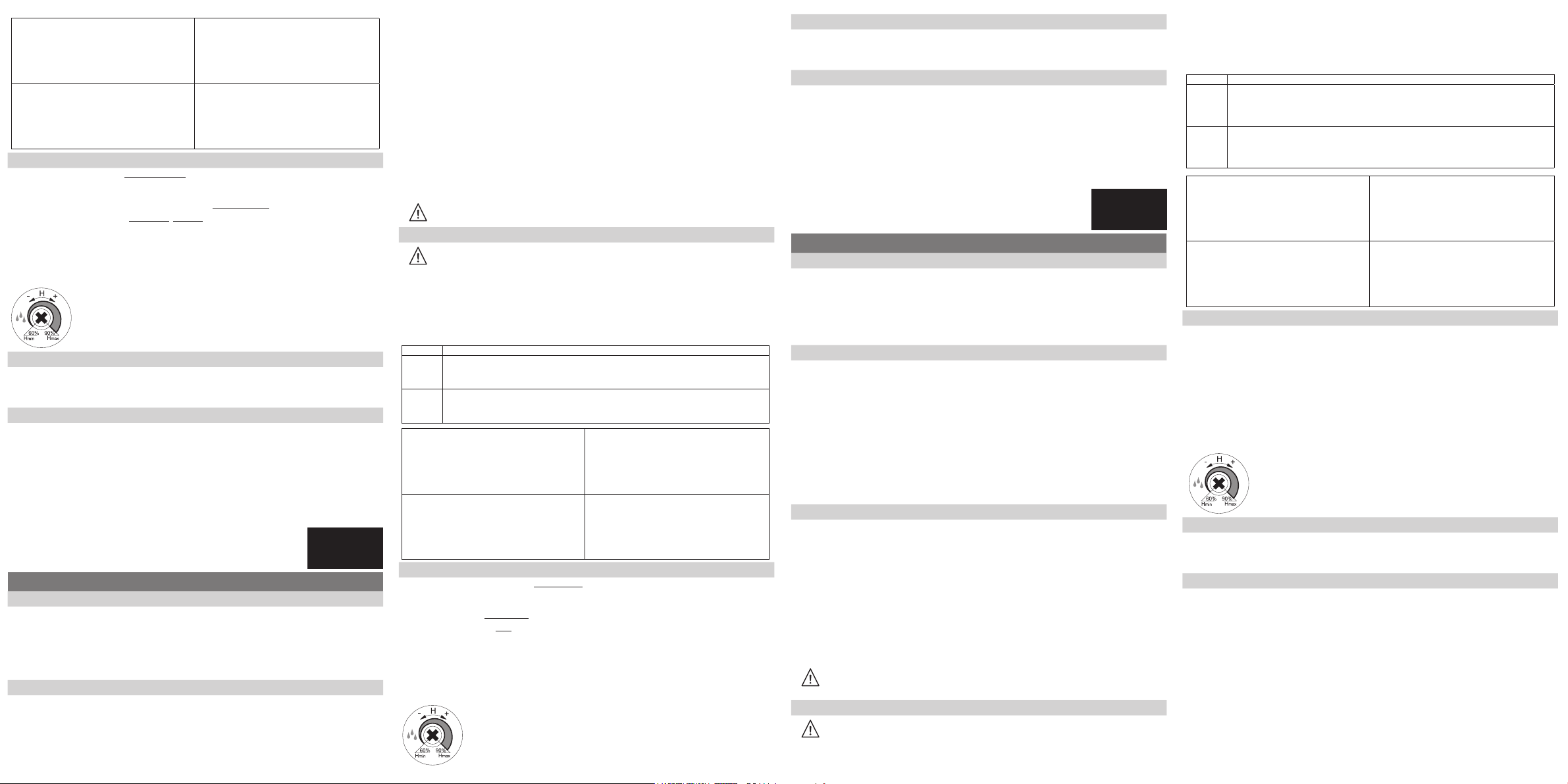
IMPORTANT! Ventilateur avec capteur d’humidité.
On les règle en tournant le potentiomètre H vers la droite ou la gauche pour augmenter ou
diminuer respectivement le niveau.
6. Service technique
Le service technique du ventilateur n’est fait qu’après un débranchement du ventilateur du réseau. Le service
comprend une épuration périodique des surfaces du ventilateur de la poussière et de la saleté.
Le nettoyage doit être fait par un tissu mou mouillé dans une solution savonneuse, ensuite essuyez la surface avec
soin.
7. Les garanties du producteur
Garantie de 5 ans à compter de la date d’achat. Le ticket de caisse servant également de certicat de garantie,
il devra être présenté en cas de recours à la garantie.
Nous garantissons le remplacement gratuit de tout radiateur montrant des vices de matière et / ou de fabrication
pendant la période de garantie, à condition que:
- Le ventilateur ait été monté conformément aux instructions de montage.
- Le ventilateur ait été correctement entretenu.
- Le ventilateur ait été installé de manière adéquate.
La garantie se limite au remplacement du radiateur après contrôle par le service technique. Les frais de démon-
tage, transport et main d’oeuvre ne sont pas couverts. Le producteur ne pourra en aucun cas être tenu responsa-
ble des dommages indirects.
Fig. 1 1 - Korps;
2 - Klammer der Leitungen;
3 - Öffnung für die Leitungen;
4 - Klemmleiste.
Fig. 3 1 - Korps;
2 - Klammer der Leitungen;
3 - Öffnung für die Leitungen;
4 - Klemmleiste.
5 - Öffnung für Befestigung des Ventilatores;
6 - Kabelführer;
7 - Potentiometer (Hydro);
8 - Potentiometer (Timer).
Fig. 2 1 - Korps;
2 - Klammer der Leitungen;
3 - Öffnung für die Leitungen;
4 - Klemmleiste.
5 - Öffnung für Befestigung des Ventilatores;
6- Lampe.
7 - Potentiometer (Timer);
Fig. 4 1 - Korps;
2 - Klammer der Leitungen;
3 - Öffnung für die Leitungen;
4 - Klemmleiste;
5 - Öffnung für Befestigung des Ventilatores;
6 - Schalter;
7 - Potentiometer (Timer);
8 - Potentiometer (Hydro).
5. Anschlussschemata
Abb.5. Falls Ihr Ventilator mit einem Feuchtigkeitssensor mit einer Zeitschaltuhr ausgerüstet ist, können Sie Abb.7.
verwenden. Diese Ventilatoren schalten sich bei einem bestimmten Feuchtigkeitsgrad (60- 90% siehe Abb.10)
automatisch ein. Nachdem der Feuchtigkeitsgrad erreicht ist, läuft die Zeitschaltuhr T noch laut der eingestellten
Nachlaufzeit (2- 30 Min.) weiter. Der Zeitschaltuhr T wird nach rechts oder links gedreht, um das Niveau zu erhöhen
oder zu verringern. Dieser Schemata gilt auch für Ventilator mit Bewegungssensor.
Abb.6. Für Ventilatoren, die mit einer Zeitschaltuhr (Nachlauf) ausgerüstet sind, und mit einem Schalter bedient
werden müssen, kann Abb.6 verwendet werden. Wann LT mit Strom wird eingeschalted ist das Ventilator wirksam.
Wann LT nicht mit Strom ist eingeschalted läuft das Ventilator noch laut der eingestellten Nachlaufzeit (2- 30
Min.). Abb.6. Falls Ihr Ventilator mit einem Feuchtigkeitssensor mit einer Zeitschaltuhr ausgerüstet ist, und mit einem
Schalter bedient werden müssen, können Sie Abb.6. verwenden. Wann LT mit Strom wird eingeschalted oder bei
eingestellten Feuchtigkeitsgrad ist das Ventilator wirksam.
Abb.7. Für alle Ventilatoren der Typen Basic, Design, Louvre und Cilinder ohne zusätzliche Möglichkeiten verwenden
Sie bitte Abb.6. Hierbei ist vom Einsatz eines zusätzlichen Schalters auszugehen.
Ventilator mit Feuchtigkeitssensor
Die Sensitivität wird geregelt, indem der Potentiometer H nach rechts oder links gedreht
wird, um das Niveau zu erhöhen oder zu verringern.
6. Die Instalthaltung
Leiten Sie die Instalthaltung des Ventilatores nur nach Ausschaltung vom Netz. Die Instalthaltung besteht in einer
periodischen Reinigung der Oberächen des Ventilatores von Staub und Schmutz.
Leiten Sie die Reinigung mit einer feuchten Gewebe, die in einer seigen Flüssigkeit angefeuchtet ist, wonach
trocknen Sie die Oberäche ab.
7. Garantien des Herstellerwerkes
Es gilt eine Garantie von 5 Jahren nach Datum Kauf. Der Kassenbon ist gleichfalls den Beweis und ist zu belegen
beim Anspruch auf Garantie.
Indem der Ventilator während der Garantiezeit nicht gut funktioniert infolge Material- und/oder Produktionsfehler,
garantieren wir kostenlose Ergänzung unter der Voraussetzung von:
- Der Ventilator an der richtigen Stelle eingebaut worden ist laut
Montageanleitung.
- Der Ventilator eine gute Wartung bekommen hat.
- Der Ventilator richtig montiert worden ist.
Die Garantie betrifft nur die Ergänzung des Ventolators, nach Kontrolle der Kundendienststelle, Kosten wie, neu
Installation, Transport und Arbeitsstunden werden nicht vergütet. Plieger kann nie für Folgeschaden angesprochen
werden.
The capacity of fans depend strongly on the shape of the airduct. Bends, type of ducting, length and kinks can
nuence the air-ow. In the most ideal situation, the fan will have a good operation with a duct length of maximum
5 meters.
Equalized sound level at 3 meter distance does not exceed 40 dBA. Fans are designed for operation at air temper-
ature within 0°C to 45°C.
3. Safety Requirements
The fans comply with the requirements according to the EU norms and directives, to the relevant EU-Low Voltage
Equipment Directives, EU-Directives on Electromagnetic Compatibility Level of protection from access to hazardous
parts and waterproof:
IPX4- Cylinder
IP24- Louvre
IP34- Design, Silent, Basic
The replacement of electric wire must be performed by a skilled electrician. Fan operation beyond the operational
temperature range as well as in rooms with ambient air containing aggressive admixes is prohibited.
For well functioning and safety matters, it is necessary to comply with your national electricity standards. The dutch
electrical wiring colours for devices are:
L = colour brown (phase) LT= colour black (switch wire)
N = colour blue (zero, 0)
Note: internal wiring colours of the fan may not necessarily match the wiring colours of your local electrical instal-
lation.
ATTENTION! Fan operation when restrictions, being able to damage or jamm blades of operation
wheel, in owing part of case, is prohibited. Precautions must be taken to avoid the back-ow of gases
into the room from the open ue of gas or other open-re appliances.
4. Preparation to device operation
Attention! All maintenance works and connection of fans are to be performed only after switching off
mains.
Direction of air-charging is to comply with direction of the arrow on the fan case. Cilinder fans are mounting in
ventilation air ducts from both ends and nipped with clamps
Fans of other models are mouted in the hole of the air duct and mounted on the wall or ceiling with dowels.
If necessary, ensure conditions to prevent free access to impeller and current-carrying parts of fan by protective
means from side of outcome (ventilation grille, protective cowl and so on).
Connection of fans to electric power supply is shown in Fig. 1-4. An order in which connection of fans should be
made is indicated in the Table shown below.
Type Operations of connection to power supply
Cylinder Remove protective grid (except for model Cilinder). Take away a protective cowl. Pass power sup-
ply cords through a hole 3, strip the wire rags at length 7-8 mm to clamp terminals 4 against stop to
the metal part of the clamp and tighten them with screws. Fix cords with the help of clip 2. Reinstall
protective cowl and grid back.
Basic,
Design,
Silent &
Louvre
Remove protective grid and cover. Pass power supply cords through a hole 3 (having cut a thin
plastic pierce on the spot of opening beforehand). Strip the wire rags at length 7-8 mm to clamp
terminals 4 agaist stop to the metal part of the clamp and tighten them with screws. Fix cords with
the help of clip 2. Reinstall cover and protective grid back.
Fig. 1 1 - housing;
2 - clip of power supply cords;
3 - holes for power supply cords;
4 - clamp terminal.
Fig. 3 1 - housing;
2 - clip of power supply cords;
3 - holes for power supply cords;
4 - clamp terminal;
5 - holes for fan mounting;
6 - lead xing rack;
7 - potentiometer (Hydro);
8 - potentiometer (Timer).
Fig. 2 1 - housing;
2 - clip of power supply cords;
3 - holes for power supply cords;
4 - clamp terminal;
5 - holes for fan mounting;
6 - light.
7 - potentiometer (Timer).
Fig. 4 1 - housing;
2 - clip of power supply cords;
3 - holes for power supply cords;
4 - clamp terminal;
5 - holes for fan mounting;
6 - potentiometer (Timer);
7 - pull cord switch;
8 - potentiometer (Hydro).
5. Diagrams
Fig.5. In case your fan is equipped with a humidity sensor in combination with a timer, g.5. should be followed.
These fans will switch on automatically if humid air (60-90%, see g.10) is sensed. After the level has been reached
(50-90%), the fan will continue operation for the time the timer has been set (2-30min.) Time can be regulated by
potentiometer T. To increase the delay, turn clockwise, and for decrease turn anti clockwise. This diagram can also
be applied to fans with a motion sensor equipped.
Fig.6. For fans equipped with timer which have to be started with an external switch g.6. can be used. The fan
will start operating as soon as it is switched on the mains. When LT is switched off the mains, the fan will continue
working for the time the timer has been set (2-30min.). Fig.6. Can also be applied to fans equipped with timer and
humidity sensor which have to be started with an external switch.The fan will start operating as soon as it is switched
on the mains or when humid air (60-90%) has been sensed. When LT is switched off the mains, or humidity level has
decreased below 60%, the fan will continue
operation for the time the timer has been set.
Fig.7. For all fans of the model Basic, Design, Louvre and Cylinder without any special features. In this situation an
external switch is applied. Note: the wire from the switch is black.
Fan with humiditysensor
The sensitivity can be regulated by potentiometer H by rotation clockwise to increase, and
anti clockwise to decrease the level.
Fans EN
USER’S MANUAL
1 Designation
Our fans are designed for ventilation of domestic and similar premises (apartments, ofces, stores, garages, kitch-
ens, bathrooms, toilets and other rooms, heated in wintertime).
Fans (but exhaust fanfor Cilinder serie) ares and are designed for wall or ceiling mounting.
Cilinder- serie fans may be used for both input and output ventilation and are to be installed in ventilation ducts.
Our fans are designed for continuous work without switching off mains.
Design of the fans is constantly improved and updated, and some models may differ from what is described in this
manual.
2. Basic Specications
Fans identication, diagrammatic representation of appearance, installation dimensions and peculiarities of
design are given in Table 1.
The fans are designed for operation from AC power supply with voltage of 220-240 V and frequency of 50 Hz.
The 12V fans are suitable for 12V - 50Hz. These fans are not equipped with a built-in transformer.
Nominal output in terms of extract air capacity is:
- for 100 mm: 82 -107 cubic meters/hour ( ±5%)
- for 125 mm: 157 - 232 cubic meters/ hour ( ±5%)
- for 150 mm: 260 - 348 cubic meters/ hour ( ±5%)
Nominal electric power of the fans is:
- For 100 mm: -9/22 W;
- For 125 mm: -16/26 W.
- For 150 mm: -24/32 W.
LE PASSEPORT
1. Le Destination
Les ventilateurs Plieger sont destinés à la ventilation des locaux ménagers et analogues (des locaux d’habitation,
bureaux, magasins, garages, cuisines, sanitaires et d’autres locaux chauffés au temps d’hiver).
Les ventilateurs (sauf la série Cilinder) sont ventilateurs d’extraction et destinés pour un montage mural ou pendant.
Les ventilateurs de la série Cilinder peuvent être utilisés pour un refoulement, ainsi que pour une aspiration et sont
installés à un canal de ventilation. Les ventilateurs Plieger sont destinés pour un travail long sans déconnexion du
réseau électrique.
La construction des ventilateurs est perfectionnée constamment, c’est pourquoi certains modèles peuvent se
distinguer à ceux décrits à ce passeport-là.
2. Les caractéristiques principales
La désignation des ventilateurs, la représentation schématique de l’apparence, dimensions d’encombrement et
de connexion, ainsi que les traits constructifs sont cités dans la Table 1.
Les ventilateurs sont destinés à la connexion au réseau du courant alternatif de la tension de 230V et de la
fréquence de 50 Hz.
Les ventilateurs 12V conviennent pour 12V - 50Hz. Ces ventilateurs ne sont pas équipés d’un transformateur intégré.
La productivité nominale selon le volume de l’air
déplacé ici fait:
- Pour 100 mm: 82 -107 m3/heure ( ±5%)
- Pour 125 mm: 157 - 232 m3/heure ( ±5%)
- Pour 150 mm: 260 - 348 m3/heure ( ±5%)
La capacité nominale électrique des ventilateurs fait:
- Pour 100 mm: -9/22 W;
- Pour 125 mm: -16/26 W.
- Pour 150 mm: -24/32 W.
La capacité des ventilateurs dépend largement de la forme du canal d’aération. Des courbes, le type et la lon-
gueur du tube, ainsi que des ambages peuvent réduire la capacité de circulation. Dans la situation la plus idéale,
un ventilateur normal fonctionnera convenablement avec une conduite d’une longueur de 5 mètres au maximum.
Le niveau de la pression sonore à la distance de 3 m n’excède pas 40 dBa. Les ventilateurs sont destinés à l’ex-
ploitation à la température de l’air dans les limites de 0ºC à 45ºC.
3. Demandes de la Sécurité
Les ventilateurs correspondent aux exigences des normes et directives du CE, aux directives correspondantes du
CE pour l’équipement d’une tension basse, les directives du CE sur compatibilité électromagnétique.
Le degré de la protection d’accès aux parties dangereuses et de pénétration d’eau :
IPX4- Cylinder
IP24- Louvre
IP34- Design, Silent, Basic
Remplacer des ventilateurs, doit être réaliser par un spécialisteélectricien, qui a un permis spécial pour les travaux
de ce type.
On interdit l’exploitation des ventilateurs en dehors de la gamme ouvrière de température, ainsi que dans les
locaux avec la présence des additions agressives dans un air.
Nos ventilateurs doivent être connectés conformément aux normes et standards en vigueur dans les pays con-
cernés. En Hollande les couleurs de lerie des appareils sont:
L = couleur brun (fase)
LT= couleur noir (l connection)
N = couleur bleu (zero, 0)
Note: Les couleurs de lerie ne doivent pas correspondre á les couleurs de lerie local de votre connection.
ATTENTION!
On interdit l’exploitation du ventilateur, qui peuvent endommager ou coincer les pales de la roue à
ailettes. On doit metre les précations pour éviter la retour de gaz à la chambre, disposé par les tuyaux
de descentes gaz fumigène open ou des autres open-gaz appareils.
4. Installation et préparation au travail
Devant tous les travaux du montage et de la connexion des ventilateurs coupez la tension du réseau,
s’il vous plaît.
La direction d’insufation d’air doit coïncider avec la direction de la èche sur le capot du ventilateur. Les ventila-
teurs Cilinder sont montés à des conduites d’air des deux côtés et sont corroyés par des colliers.
Extracteurs FR