85 mm {3-11/32 inches}
(85.7 mm {3-3/8 inches})
ø
25.4 mm
{
ø
1 inch}
*5
85 mm
{3-11/32 inches}
(85.7 mm
{3-3/8 inches})
138 mm
{5-7/16 inches}
ø
25.4 mm
{
ø
1 inch}
*5
138 mm
{5-7/16 inches}
83.5 mm
{3-9/32 inches}
46 mm
{1-13/16 inches}
ø
25.4 mm
{
ø
1 inch}
*5
63 mm
{2-15/32 inches}
ø
25.4 mm
{
ø
1 inch}
*5
63 mm
{2-15/32 inches}
83.5 mm
{3-9/32 inches}
ø
25.4 mm
{
ø
1 inch}
*5
108.5 mm
{4-9/32 inches}
70 mm
{2-3/4 inches}
ø
25.4 mm
{
ø
1 inch}
*5
Position A Position D
Position B
Position C
Position E
Position F
Attachment plate (accessory)
Fixing screws for attachment plate: x4 (M4, locally procured)
T
46 mm {1-13/16 inches}
83.5 mm
{3-9/32 inches}
Installation
Step2 Fixing the brackets
The installation tasks are explained using 4 steps.
There are 4 methods to install the camera to a ceiling or wall as described below
required parts for each installation method before starting the installation. The following are the
requirements for the various installation methods.
Installation method
Recommended
screw
Minimum pull-out
strength (per 1 pc.)
[1] Mount the camera on the two-gang junction
box using the attachment plate.
M4 screws x 4 196 N {44 lbf}
[2] Directly mount the camera onto the ceiling or
wall using the attachment plate (when wiring
can be installed in the ceiling or wall).
M4 screws x 4 196 N {44 lbf}
[3] Mount the camera onto the ceiling or wall using
the base bracket (when conduits are used for
wiring, or when there is no space available for
wiring in the ceiling or the wall).*
1
M4 screws x 4 196 N {44 lbf}
[4] Mount the camera embedded to a ceiling using
the WV
705 g {1.55 lb}).*
1
*
2
—
There is suffi cient
strength in the ceiling
*1 fi x the attachment plate to the base bracket or
WV
*2
For information on how to mount the camera embedded to a ceiling using WV
to the Instruction Manual provided with the WV
IMPORT
Procure 4 screws (M4) to secure the attachment plate (accessory) or base bracket ●
(accessory) to a ceiling or a wall.
The minimum required pull-out capacity of a single screw or anchor bolt is 196 N ●
{44 lbf} or more when mounting with the installation method [1] to [3] above.
When mounting the camera on a concrete ceiling, use an ●
securing. (Recommended tightening torque: 1.6 N·m {1.18 lbf·ft})
Select screws according to the material of the ceiling ● or wall that the camera will be
mounted to. In this case, wood screws and nails should not be used.
If a ceiling board such as plaster board is too weak to support the total weight, the ●
area shall be sufficiently reinforced.
[1] Using a two-gang junction box
[2]
Directly mount the camera to the ceiling or wall using the attachment plate
[3] Mount the camera to a ceiling or a wall using base bracket
<
or wall for wiring>
The base bracket can be fixed in any of the following 6 screwing positions
according to ceiling and wall conditions. Match the hole used when
installing the camera to any of positions
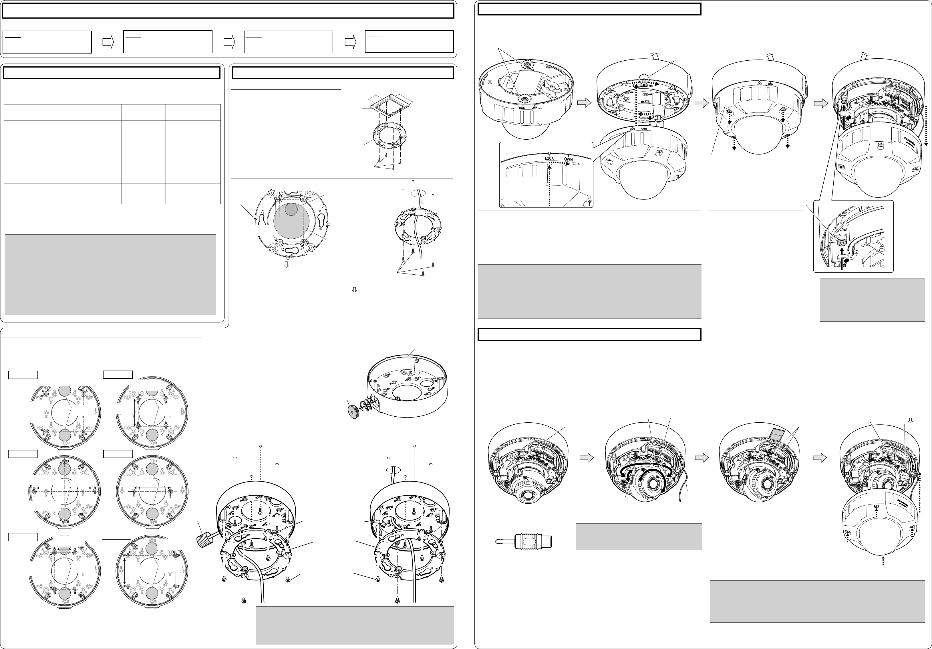
<Mounting the base bracket>
q
the conduit by using a hexagon wrench
(ISO 2936, width across flats S=5 mm
{3/16 inches}).
w
the base bracket.
Attachment plate (accessory)
Fixing screws for attach-
ment plate: x4 (M4, locally
procur
ø25.4 mm
*3
{1 inch}
ø73 mm
*4
{2-7/8 inches}
*5 The wiring hole diameter is 25.4 mm {1 inch}. Select any of the 2 base bracket fixture holes of
G
template B when installing the base bracket.
direction of the camera can be adjusted in 90° increments.
*6 When attaching the base bracket to a one-gang junction box in Position E, secure the base bracket
with 2 screws (M4,
locally procur
).
IMPORT
If open wiring is conducted, be sure to use conduits and run the cables inside ●
the tubes to protect the cables from direct sunlight.
Installation work shall be such that there is no exposure to water into the ●
architecture through the conduits having been joined.
Step1
Make sure all items are prepared
before beginning installation.
Step2
Mount the brackets to a ceiling or
wall
Step3
Connect cables, and then attach the
camera to the mount bracket.
Step4
Adjust the angle of view and focus,
and then mount the enclosure.
FRONT
Cap for the female
thread for the con-
duit
Base bracket (accessory)
Fixing screws (M4x4, locally
procur
Minimum pull-out
strength: 196 N {44.06 lbf}
(per 1 pc.)
Fixing screws for attachment
plate: x4 (accessory)
(Recommended tightening
torque: 0.78 N·m {0.58 lbf·ft})
Attachment plate
(accessory)
*3
If the mounting direction of the camera has already been determined
Align the FRONT direction (the direction of FRONT marker on the camera that indicates the
installation direction when installing the camera) of
F
template
drill through a 25.4 mm {1 inch} diameter hole.
*4
the direction of the camera after it has been installed
If you want to be able to change the direction of the camera, drill through a 73 mm {2-7/8 inches}
diameter hole in the center
90° increments.
Step3 Mount the camera to the attachment plate
Step4 Adjustment
q
mounting screws on the rear side
of the camera.
w
the instructions in “Making connections”, and
mount the camera by inserting the attachment
mounting screws into the holes of the attach-
ment plates.
eLoosen the enclosure fi xing screws. r
and secure the camera using camera
fi xing screws.
Note:
After cables have been connected to the camera, align the OPEN mark of the enclosure ●
side panel with the protruding part of base bracket, insert 2 attachment mounting screws
into the attachment plate, and rotate the camera approximately 15°. The LOCK mark is
moved to the protruding part of base bracket and the camera is temporarily secured.
(When directly attaching the attachment plate to a ceiling or wall, align the OPEN mark to
the tab position of the attachment plate.)
*The fixing angle of the camera can be rotated in 90° increments
.
Note:
Loosen 4 enclosure fixing screws ●
using the bit (accessory).
IMPORT
Be sure to tighten the camera fixing ●
screw
cause camera trouble due to camera
falling. (Recommended tightening
torque: 0.78 N·m {0.58 lbf·ft})
q
connecting a LAN cable or a 12 V DC
power cable, and then remove the protec-
tion fi
w
plug (accessory) to the MONITOR OUT
terminal of the camera, and then connect
the monitor for adjustment with a RCA
cable (locally procured).
The camera is set to be connected to the ●
NTSC monitor for adjustment at factory
shipment.
T●
button for about 2 seconds. When the flashing SD MOUNT
indicator goes out, you can remove the SD memory card.
After the SD memory card has been replaced, press the ●
SD ON/OFF button, and make sure the SD MOUNT
indicator is continually lit. (If you replace both SD memory
cards, press the SD ON/OFF button after replacing the
cards.)
If you do not press the SD ON/OFF button after replacing ●
the SD memory card, the SD MOUNT indicator is
continually lit approximately 5 minutes later
When adjusting the viewing angle, make sure not to touch ●
the light-blocking rubber ring or IR LED cover
or dirt can reduce the quality of viewed images.
IMPORT
After adjusting the angle of view●
slot tilting lock screw
(Recommended tightening torque: 0.59 N·m {0.44 lbf·ft})
e
tilt table, pan table, and azimuth adjust-
ment ring, and then adjust the viewing
angle by pressing the WIDE or TELE
buttons, and tighten the cross slot tilting
lock screw fi nally
Horizontal position (Panning): ± 180°
V
Image tilt adjustment:
-45°(Left) to +300°(Right)
r
if necessary
t
after adjusting the focus by pressing the
AF button.
y
(Align the mark on the camera body
with the LOCK line on the enclosure
and then mount the enclosure to the
camera body at a straight angle.)
E MONITOR OUT conversion plug
(accessory)
Note:
When the screen size is adjusted using the WIDE ● button or TELE button, the camera’s focus is
automatically adjusted with the basic focus adjustment function each time the WIDE button or
TELE button is pressed.
Depending on the vertical position (tilting) range or the optical zoom, it must be noted that the ●
shadow of the enclosure may be projected.
When adjusting the viewing angle for cameras mounted to ceilings, the enclosure and installation ●
auxiliary wire may be displayed on the screen depending on the direction the camera is facing.
Move the enclosure and installation auxiliary wire so that they are not displayed on the screen.
When mounting the camera on a ceiling, adjust the tilt angle so that the T●
always comes to the top side.
When the camera is installed to a wall, the image is reversed in the default settings. T●
way the image is displayed, rotate the azimuth adjustment ring 180° clockwise, or select “On” for
“Upside-down” from the setup menu. For information about performing the “Upside-down” setting
from the setup menu, refer to the Operating Instructions (included in the CD-ROM).
Remove the camera using the reverse order of the installation procedures.●
IMPORT
Securely tighten all the fixing screws (x4) of enclosure. Otherwise, camera dropping may ●
result in injury
Defocus may be caused by the reinstalled enclosure. In this case, perform the auto focus ●
function from the setup menu.
Remove the cover film from the dome cover●
Approx. 15°
Enclosure
Camera fixing screw
Attachment mounting screws
IMPORT
Disconnect the 12 V DC power source and PoE power source to prevent power from being ●
supplied during mounting work.
Enclosure is fixed at the installation auxiliary wire to the camera body●
remove the installed auxiliary wire.
For installations on the wall, to prevent water from accumulating on the surface of the ●
dehumidifying device, install the camera so that the dehumidifying device does not face up.
If water accumulates on the surface of the dehumidifying device, it cannot function properly
<
ceiling or wall for wiring>
The female thread for conduit is compliant ●
with
or ISO 228-1 (parallel pipe threads) G3/4.
*
6
After installing the camera, refer to “Configure the settings of the camera (leaflet)” and
perform the camera settings.
T
of the attach-
ment plate
(x4)
Conduit
Protruding part (x4)
Insert the SD memory card with its label ●
facing down.
Refer to the Operating Instructions on the ●
provided CD-ROM for further information
about the SD memory card settings.
46 mm
{1-13/16 inches}
83.5 mm
{3-9/32 inches}
NTSC P
WIDE button
AF button
SD1, SD2
TELE button
Direction marker
for installation
(FRONT
)
Tilting lock screw
Installation auxiliary
wire
The enclosure is
rotated and the
camera is tem-
porarily secured.