JA-83M CZ / EN / DE / SK / RU MLL51000
JABLOTRON
JA-83M
CZ Bezdrátový magnetický detektor otevĜ ení
EN Wireless magnetic door detector
DE Funk - Öffnungsmelder
SK Bezdrôtový magnetický detektor otvorenia
Ɋɍɋ Ȼɟɫɩɪɨɜɨɞɧɨɣ ɦɚɝɧɢɬɧɵ ɞɟɬɟɤɬɨɪ ɨɬɤɪɵɬɢ
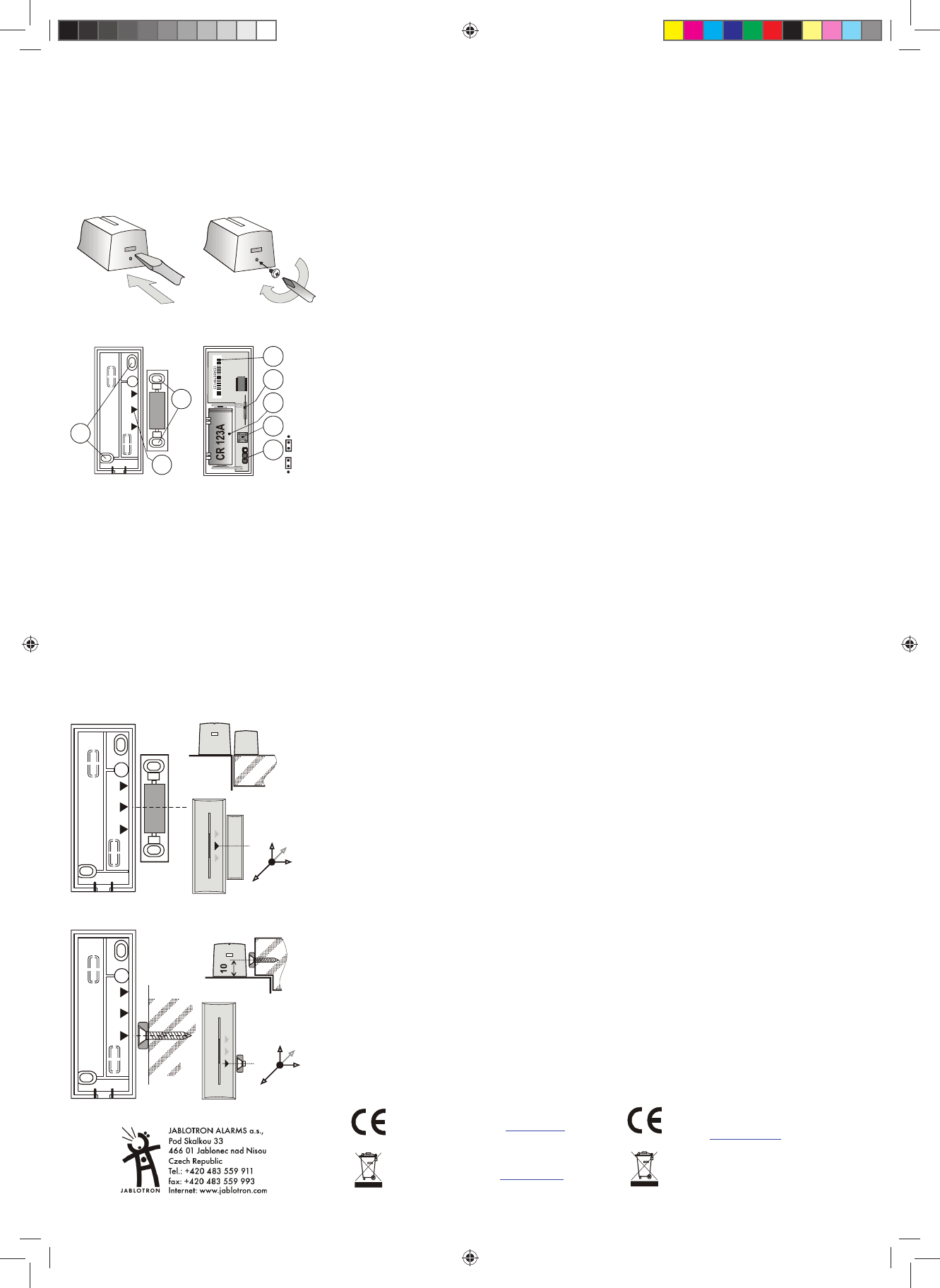
fig. 1 fig. 2
B A B
1
2
3
+
DEL
7
4
5
6
INS
8
fig. 3 fig. 4
CZ 1. moČní vysíla þ e; 2.
pro upevnČ ní magneþíslo;
5. jazýþ kový kontakt;þ;
8. nastavení reakce
EN 1.
magnet A, 3.
5. reed contact;
DE 1.
2.
Position des Mag
5. Schutzrohrkon CR123A; 7. Sabotag
8. Einstellen der
SK
1.
otvory pre upev
A,B; 4. sériové þ íslo; 5. jazýþ kový kontakt; 6.
7. sabotážny
Ɋɍɋ 1. ɦɨɧɬɚɠɧɵɟ ɨɬɜɟɪɫɬɢɹ ɞɥɹ ɤɪɟɩɥɟɧɢɹ ɩɟɪɟɞɚɬɱɢɤɚ ;
2. ɦɨɧɬɚɠɧɵɟ ɨɬɜɟɪɫɬɢɹ ɞɥɹ ɤɪɟɩɥɟɧɢɹ ɦɚɝɧɢɬɚ A, 3. ɩɨɡɢɰɢɹ
ɦɚɝɧɢɬɚ A,B; 4. ɡɚɜɨɞɫɤɨɣ ɧɨɦɟɪ; 5. ɝɟɪɤɨɧ ; 6. ɛɚɬɚɪɟɣɤɚ
CR123A; 7. ɬɟɦɩɟɪɧɵɣ ɤɨɧɬɚɤɬ ; 8. ɧɚɫɬɪɨɣɤɚ ɪɟɚɤɰ.
B A B
A
15
40 /
20 /
20 /
fig. 5
B A B
B
10
25 /
20
5/
10 /
fig. 6
ýESKY
Detektor JA-83M je
Jablotron. Je urþ en k detekci otevĜení dve Ĝí, oken apod. Detek
komunikuje bezdrátovČ a je napájen z
Instalace
Výrobek má mont
výrobce.
Vyberte vhodné místo pro instalaci. Detektor reag
oddálení magnþ ást se montþ ást dvĜ í
(okna) aþ ást. VyhnČ te se montáži pĜ ímo
na kovoĜedm Č ty (ovlivĖ ují negativČ þinnost magnetické
senzoru i rádiov
1. OtevĜete kryfig. 1 ).
2. PĜ išroubujteþ ást dveĜ íþky
A,B na tomto plastu vþ ují umíČ ní magnetu (fig. 3).
3. PĜ išroubujte þ ást dveĜ í (okna). Magnet
v plastovém Ĝ e umíst Č te st Ĝ edem pouz
prstencový magnet musí
magnetu od vþ ásti má býĜ i zavĜ ených dveĜ ích co
nejmenší. VzdálenosĜ i oddálení magne
všech osách a pro
podklad jsou uvfig. 5 a fig. 6 . Pozn. Pro
výškové nastavení A m
4. Nauþ te detektor do úĜ edny (pĜijíma þ e). ěi ć te se návodem
k ústĜ edn
Č (p Ĝijíma þi). U þící signál je vyslán ve chvíli p Ĝipojení
baterie. Pozn. Budete-li detektor do p Ĝijímþ e u þ it poté, co už
mČ l zapojenou baterČ te a
uvolnČ te kontakt krytu
potom proveć te uþ ení.
5. Nastav
6. Vysílací þást nasa ćte na zadní plastČ te.
7. Vyzkoušejte sp
8. Západku lfig. 2 ).
Nastavení
Propojka INS / DEL (fig. 4) ur þuje zĜ í
cestČ do domu a poskyodchodové a pĜíchodové
zpoždČ ní = pozice DEL. Naopak pozice INS znamená
okamžitou reakci systému. Pozn. Nastaven
pĜ i použití s Ĝ ednou OASiS s nastavenou reakcí NATUR. Je-li
v ústĜ edn Č detektoru
detektor s Ĝijíma þ em UC-8x neb
pĜ epína þ e žádný
Detektor má dva režimy funkce, které jsou indikov
nebo dvČ ma bliknutími signálky pĜi vložení baterie.
Jedno bliknutíhlásí otevĜ ení i
zavĜení . Je tak možné sledĜ í. DvČ
bliknutí znamepouze pĜ i otevĜení
(oddálení mag
PĜ epnutí režimu prov
spínaþ krytu, þ uvolníte 3-5 sekund po
vložení bateri
právČ zvoleného rež
Testování detektoru
Po dobu 15 miĜení kr
signálkou. ÚstĜ edna umož Ė uje v
signál detektoru vþ etnČ mČĜení jeho kvality.
VýmČ na baterie v de
Systém kontroluje stĜiblíží její vybití,
informuje uživatele (pĜípadn Č i servisního technika)
komunikátorem sy
každou aktivaci bliknutím signálkyþ ujeme vym Čnit
do 2 týdnĤ . VýmČ nu
Po výmČn Č baterie otestujte funkci detektoru.
Pozn. Je-li do detektslabá baterie, bude j
signálka cca 1 . Pak þ ne detektor fu
bude hlásit vybit
ale odevzČ rného m
Odebrání detektoru ze systému
Systém hlásí pĜ ípadnČ
demontujete, Ĝ ednČ.
Technické p
Napájení lithiová baterie typ CR-123
Typická životnost bater cca 3 roky (pro max. 20 aktivací dennČ)
Komunikaþ ní pásmo 868 MHz, protok
Komunikaþ ní dosah cca 300m (pĜ ímá vi
Typická rozpínací/spí fig. 5 a fig. 6
RozmČ ry vysílací þ ást 75 x 31 x
magnet A: 56 x
ProstĜ edí dle ý SN EN 50131-1 II. vnitĜ ní všeobecné
Rozsah pracovní -
Klasifikace stupeĖ 2
dle ýSN EN 50131-1,ýSN EN 50131-2-6, ýSN EN 50131-5-3
Dále splĖ uje ý SN ETSI EN 300220,ý SN EN 50130-4,
ý SN EN 55022, ý SN EN 60950-
Podmínky prov ý TÚ VO-R/10/06.
DetektoČ s na Č j se
vztahujíĜízení vlá
þ. þ ení. Originál
prohlášČ jewww.ja v
poraden
Poznámka: Výrobek, a þkoliv
škodlivé materiálĤ , ale
pĜ edejte na sb Č rné místo el
PodrobnČ jší inwww.
ENGLISH
The JA-83M is a component o
is designed to det
battery-pow
protocol.
Installation
Installation shall only be undertak
certificate issued
Choose the suitable place for dete. The
detector reacts to the removal of its magnet unit. The electro
should be installed ont
and the magnet
a metal frame as met
sensor and radio c
1. Open the detector cover by prfig. 1 )
2. Screw the rear cover
marks A and B showfig. 3 )
3. Attac
standard magnet in a
the whorl shap
the detector should be as small as pos
door/window is closed. Ifig. 5 and fig. 6 are
shown the reaction area
axes of movement and o
surface. Note: Use the supplied
possible height dif
4. Enroll the detector into the control pa
manual for more i
when the battery is inNote: To enroll a detector a
having already connected
battery, and press
any remaining charge
5. Set the detector’s reacti
6. Mount the front cover onto
7. Test the detector’s function.
8. The tab can be fixed usingfig. 2 ).
Settings
The DEL position o
for detectors installed INS position allows
the detector to i
is armed. Note: This DIP switch (INS/DEL) only has an effect if
the detector has anatural reaction assigned to its ad
the Oasis control panel. It also has no effect when used with a
UC-8x or AC-8x receiver.
The detector has two different modes. Th
by one or two short flash when the battery
One flash means t
door or window
windows. Tw
detector indic
The mode can be set (
pressed while installing the batte
Testing the detector
15 minutes after closi
detector trigg
can be measured
Battery replacement
The detector moni
sent to the control
detector continues t
detector with a
be delayed by
qualified technicia
Note: If a partly discharged battery is in
start flashing for one minute. Then the detector will work but
the Lo Bat signal will
batteries should not
according to local regulations.
Removing the detector from the system
If a detector is r
The detector has to be delete
intentional rem
Technical parameters
Voltage: Lithiu
Typ. battery lifetime: approx. 3 years
Communication ba 868 MHz, Oasis pro
Communication r approx. 300m (op
Typical sensitivi see fig. 5 andfig. 6
Dimensions: transmitter part 7
A magnet: 56 x 16
Operational env
II. Indoor general
Operational te -10 to +40 °C
Classification: grade 2
according to: EN 5
Complies with: ETSI EN 300220,
and
Can be operated ERC REC 70-03
Jablotron Ltd. her is
in compliance with the essen
other relevant prov
The original o
found at www.
harmful mate
product to the dealer
after use.
MLL51000-print.indd 1MLL51000-print.indd 1 7.8.2009 10:16:547.8.2009 10:16:54