WARNING: Installation must be performed by qualified technical
personnel and must be in accordance with all national and local
mechanical and electrical codes.
Installation
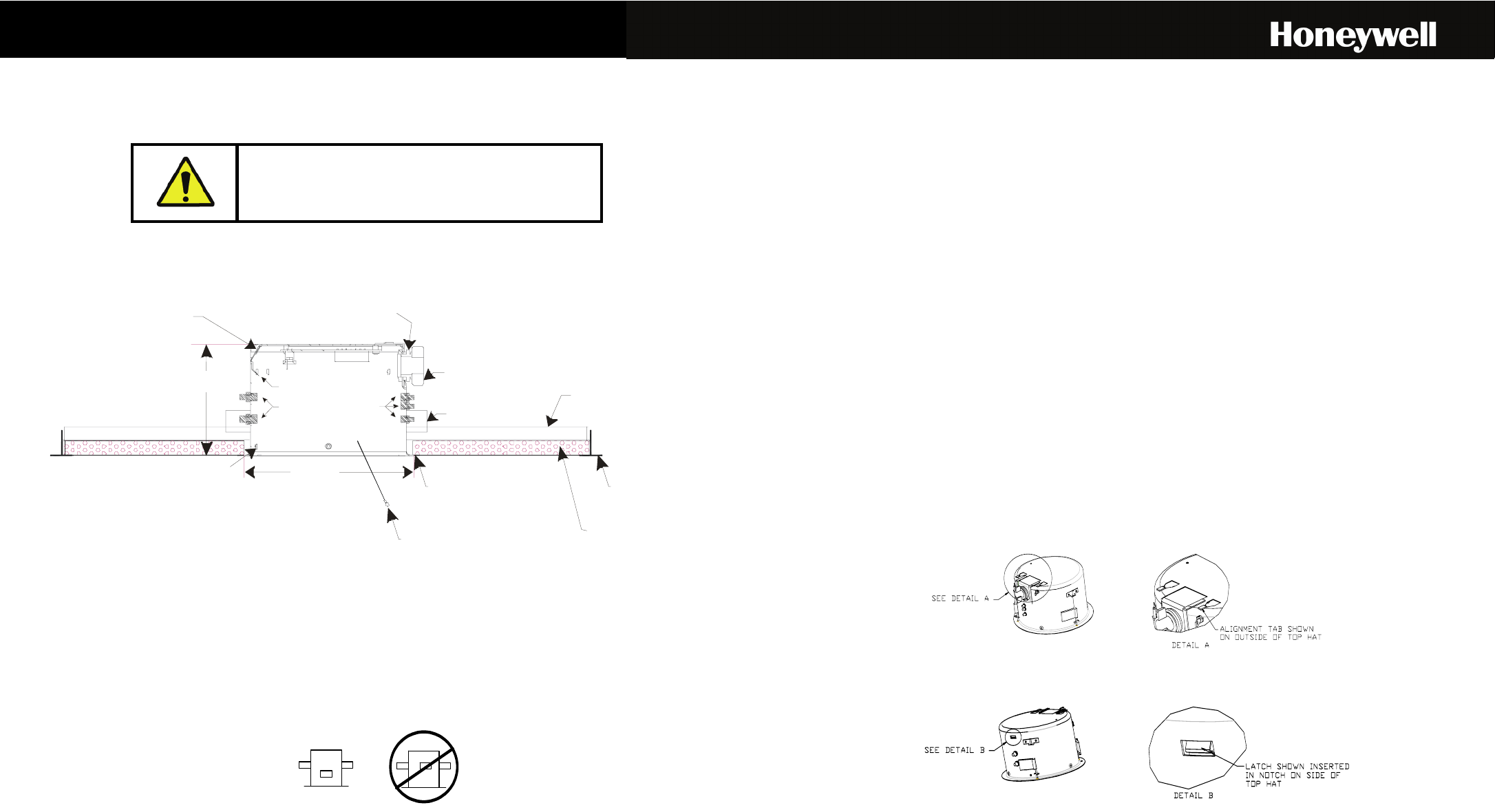
Perform the following steps to install a dropped ceiling housing. Refer to Figure 1.
HOUSING
LOWER DOME
MOUNTING POSTS
(3 PLACES)
ATTACH LANYARD TO BOTTOM
TURN SCREW CLOCKWISE TO
EXTEND SUPPORT CLAMPS AND
SECURE DOME TO CEILING
(TYPICAL 3 PLACES)
WING TAB (3 PLACES)
CABLE CLAMP
SAFETY CABLE TIE POINT
(METAL TAB WITH HOLE ON SIDE OF CAN)
CONNECT SECURELY TO BUILDING
SUPPORT STRUCTURE
DROPPED CEILING PLATE
SPRING LATCH
(RELEASES TOP PLATE)
SCAN ALIGNMENT STUDS
CUSTOMER 2 FT
SPAN DROPPED
CEILING GRID
SUPPORTS
.62 (15.7) DROPPED
CEILING TILE
CUT-OUT IN CEILING TILE
7 5/8” DIA.
(193.8)
APPROX 5.00
(127)
Figure 1: Dropped Ceiling Housing Installation
1. Remove the ceiling panel (2’x4’ or 2’x2’) at the dome location.
2. Place the ceiling tile on the dropped ceiling plate. Trim the ceiling tile so you can press the ceiling tile into the dropped ceiling plate.
3. Cut a hole in the ceiling tile flush with the hole in the center of the plate.
4. Secure a safety cable (supplied by installer) to a building support structure. Honeywell Video Systems recommends using 3/32” plastic
coated aircraft cable (part 849518-0311) and looping sleeves (part 849511-0057). These parts can be ordered from the Honeywell Video
Systems parts department.
5. Place the housing in the ceiling mount. The space between the wing tabs on the housing and the housing flange should be greater than the
thickness of the ceiling tile and the mount. Make sure the wing tabs on the housing are staggered so the tabs are not at the same height.
6. Position the wing tabs flat against the housing. Push the housing through the hole in the ceiling tile and the mount (some jostling is
required). Using a screwdriver, turn the three screws in the housing clockwise to rotate the tabs out and tighten the tabs against the ceiling
mount.
7. Attach the safety cable (from the building support structure) to the housing by threading the cable through a looping sleeve, through the hole
in the tab (beside the conduit fitting) on the housing , and then through the looping sleeve again. Secure by crimping the looping sleeve.
The safety cable tab on the housing can be rotated as needed for clearance in the ceiling.
8. Place the ceiling tile with the plate and the housing on the ceiling support grid.
Wiring
The top plate in the top hat can be lowered for ease of installing the field wiring. Pull the spring latch (refer to Figure 1 for location) on the plate
away from the housing to release the plate and then lower the plate down.
1. Feed the field wiring (data, power, video, and alarm inputs) through the housing and then through the cable clamp on the top plate.
2. Install the 24Vac power wires, data wires, and alarm wires on the correct positions on terminal strip TB1 and TB2. Refer to Figure 2 for
standard wiring (2-wire RS485 and video over coax) and refer to Figure 3 for Unshielded Twisted Pair (UTP) option wiring (video and data
over UTP wire). The terminal strip is labeled to show the function of each position. Note: Do not connect the data cable shield at the terminal
strip. The terminal strip accepts 18-24AWG wire. If larger or smaller field-run wire is required, an 18-24 AWG wire must be spliced onto the
field wire for insertion into the terminal strip.
a. Flip up the tab on the terminal strip.
b. Strip the insulation on the wire back approximately 7/16”.
c. Insert the wire fully in the hole on the terminal strip to ensure a good contact and to ensure it does not short to adjacent wires.
d. Push the tab down to secure the wire.
3. If standard wiring is used, connect the video coaxial cable to the BNC connector. The installer must supply the mating BNC connector. If the
UTP option is used, the BNC connector is not used. The video is connected to terminal strip TB3 using one pair of unshielded twisted wire.
Refer to Figure 3.
4. Feed the excess cabling from the terminal strips back through the cable fitting and tighten the cable clamp.
5. Set the termination jumpers. If this is the last dome in a daisy-chain wiring loop, the receive and transmit communication lines must be
terminated. All intermediate domes must be unterminated. If this is the only dome on a data line, the receive and transmit communication
lines must be terminated. Install Jumper W1 on pins 1 and 2 (terminated) to terminate the data. Install Jumper W1 on pins 2 and 3
(unterminated) to unterminate the data. Jumper W2 should be on pins 2 and 3 for all domes.
6. Set the communication jumpers.
Standard Interface Board - The HD6 is designed for 2-wire communication. Jumpers W3 and W4 must be placed in the 2-wire position (pins
1 and 2) for all applications except 2-wire half duplex.
UTP Option Interface Board – Jumpers W3 and W4 must be in position 1 and 2.
7. Secure the top plate in the top hat.
a. Align the tabs on the plate with the slots in the top hat. Refer to Detail A below.
b. Push the field run wiring back through the access hole in the top hat.
c. Push the plate up until the spring latch catches and locks the top plate. Refer to Detail B below.
8. Refer to the HD6 quick start guide or HD6 User Manual to install the scan, the inner liner and bottom dome.
Gebruikershandleiding.com neemt misbruik van zijn services uitermate serieus. U kunt hieronder aangeven waarom deze vraag ongepast is. Wij controleren de vraag en zonodig wordt deze verwijderd.
Product:
Spelregels forum
Om tot zinvolle vragen te komen hanteren wij de volgende spelregels:
lees eerst de handleiding door;
controleer of uw vraag al eerder door iemand anders is gesteld;
probeer uw vraag zo duidelijk mogelijk te stellen;
heeft u een probleem en al geprobeerd om dit op te lossen, vermeld dit erbij aub;
heeft u een oplossing gekregen van een bezoeker dan horen wij dat graag in dit forum;
wilt u een reactie geven op een vraag of antwoord, gebruik dan niet dit formulier maar klik op de knop 'reageer op deze vraag';
uw vraag wordt direct op de website gezet; vermijd daarom persoonlijke gegevens in te vullen;
Belangrijk! Als er een antwoord wordt gegeven op uw vraag, dan is het voor de gever van het antwoord nuttig om te weten als u er wel (of niet) mee geholpen bent! Wij vragen u dus ook te reageren op een antwoord.
Belangrijk! Antwoorden worden ook per e-mail naar abonnees gestuurd. Laat uw emailadres achter op deze site, zodat u op de hoogte blijft. U krijgt dan ook andere vragen en antwoorden te zien.
Abonneren
Abonneer u voor het ontvangen van emails voor uw Honeywell HDT0D00x HD6 bij:
nieuwe vragen en antwoorden
nieuwe handleidingen
U ontvangt een email met instructies om u voor één of beide opties in te schrijven.
Ontvang uw handleiding per email
Vul uw emailadres in en ontvang de handleiding van Honeywell HDT0D00x HD6 in de taal/talen: Nederlands, Duits, Engels, Frans, Italiaans, Spaans als bijlage per email.
De handleiding is 1,62 mb groot.
U ontvangt de handleiding per email binnen enkele minuten. Als u geen email heeft ontvangen, dan heeft u waarschijnlijk een verkeerd emailadres ingevuld of is uw mailbox te vol. Daarnaast kan het zijn dat uw internetprovider een maximum heeft aan de grootte per email. Omdat hier een handleiding wordt meegestuurd, kan het voorkomen dat de email groter is dan toegestaan bij uw provider.
Uw handleiding is per email verstuurd. Controleer uw email
Als u niet binnen een kwartier uw email met handleiding ontvangen heeft, kan het zijn dat u een verkeerd emailadres heeft ingevuld of dat uw emailprovider een maximum grootte per email heeft ingesteld die kleiner is dan de grootte van de handleiding.
Er is een email naar u verstuurd om uw inschrijving definitief te maken.
Controleer uw email en volg de aanwijzingen op om uw inschrijving definitief te maken
U heeft geen emailadres opgegeven
Als u de handleiding per email wilt ontvangen, vul dan een geldig emailadres in.
Uw vraag is op deze pagina toegevoegd
Wilt u een email ontvangen bij een antwoord en/of nieuwe vragen? Vul dan hier uw emailadres in.