34 Ferm
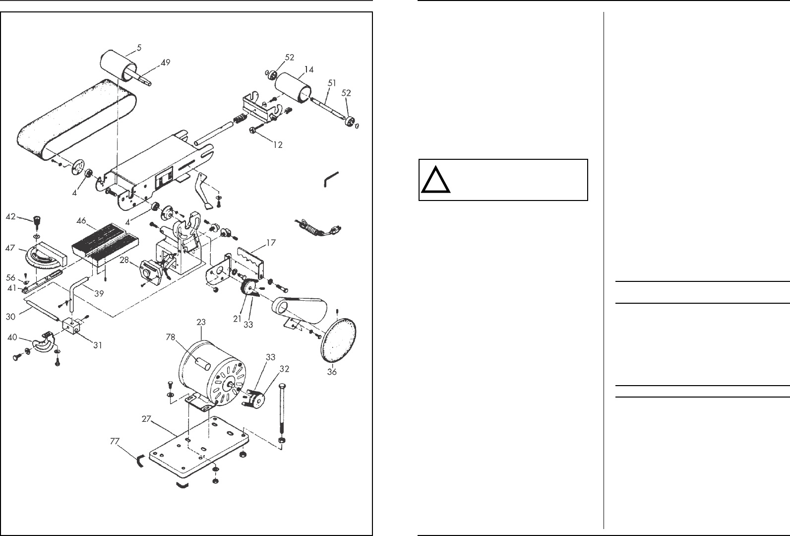
EXPLODED VIEW
Ferm 3
disc with the socket bolt in the side of the disc.
- Place the work plate (12) with the shaft in the machi-
ne frame and secure the work plate with the bolt in
the side of the machine frame. Check with a 90° sash
angle on the work plate and against the sanding disc if
the angle is exactly 90°.
- If necessary, adjust this angle with the calibration indi-
cator.
- The mitre scale (13), which is also supplied separate-
ly, can be placed on the work plate (13). With the use
of this mitre scale the angle of grinding can be deter-
mined precisely.
- The fence (8) for the belt sander can be placed behind
the uppermost bolt of the V-belt guard. In this way
the workpiece can be held firmly against the belt, wit-
hout great hazards.
To prevent the workpiece or your fingers
from getting caught between the work plate
(12) and the sanding disc (11), the space be-
tween work plate (12) and sanding disc (11)
must not exceed 1.6 mm.
THE CHOICE OF SANDING PAPER
With coarse sanding paper (P 60) generally most of
the material can be removed, and fine sanding paper
(P 150) is then used for finishing. An uneven surface is
first treated with coarse sanding paper and sanded
until it is even. Subsequently medium-coarse sanding
paper (P 100) is used to remove the scratches caused
by the first type of paper used. Fine sanding paper (P
150) is used for finishing. The sanding needs to be con-
tinued until the surface is smooth.
THE PLACING OF THE SANDING PAPER (SEE
FIG. 2)
When the sanding machine is held with the sanding
disc turned towards you, the sanding belt moves from
right to left along the upper part of the machine. Be-
cause of this turning direction the workpiece will be
pressed against the right side of the fence. An arrow
on the inside indicates the right direction of running
of the sanding belt (see drawing). If no direction is in-
dicated, the sanding belt must be placed in such a way
that the elevated part of the seam is placed into the
turning direction of the belt. So it is very important
that the sanding belt is placed in the correct way. The
machine uses standard 100 x 915 mm sanding belts
(nr 7):
- Remove the plug from the mains socket;
- Push the clamping handle completely to the right
to take away the tension of the transport rollers;
- Push the sanding belt along both of the transport
rollers, starting from the back of the machine;
-
Push the clamping handle completely to the left.
Now the sanding belt should be completely tight.
- Turn the transport roller exactly in a right angle to
the direction of the sanding belts with the use of
the winged nut at the right roller. The direction of
running of the belt is adjusted correctly if the sides
of the sanding belt are running parallel to the be-
aring plate.
THE SANDING DISC
Paper or “velcro” plates are used for the sanding disc.
The standard diameter is 150 mm. The plates are self
adhesive.
VERTICAL PLACING OF THE SANDING BELT
(SEE FIG. 4)
For more flexibility of the sanding belt its bottom side
can be used, because there is no bearing plate. For an
easy reach of this bottom side the sanding belt can be
placed in vertical position:
- Loosen the two nuts (1) at the front of the sanding
machine, around the left transport roller shaft,
with the use of an open-end spanner;
- Push the sanding belt up in the position desired;
- Fasten the two nuts (1) again;
- The workpiece can now rest on the worktop in-
stead of on the sanding belt;
- The work plate which is used for the sanding disc
can now be pushed with the shaft into the hole of
the machine frame, at the left side of the sanding
machine;
- Fasten the bolt at the back of the machine;
- The work plate can now be used as support for
the sanding of the work piece against the sanding
belt.
5. PUTTING THE MACHINE INTO
OPERATION
- Press the switch into position ‘1’ to put your sanding
machine into operation.
- To switch off the machine the same switch needs to
be pressed to position ‘0’.
- Always keep the mains cable away from moving parts.
- There is no need to apply any pressure with the
workpiece, because this only slows down the speed
of the sanding disc.
6. SANDING OPERATION
The sanding belt and disc supplied with this sanding ma-
chine are suitable for the sanding of metal, wood or syn-
thetic surfaces. The workpiece should always be held
firmly during sanding. No extra pressure is needed. Gui-
de the work piece up and down over the sanding belt, in
order to prevent the sanding belt and plate from wearing
through in one place. Round objects can be sanded at the
ends of the sanding belt (see Fig. 3). Work pieces which
are longer than the sanding machine can be sanded by re-
moving the fence.
NB: To prevent splintering, wood always needs to be
sanded in the longitudinal direction of the grain.