TC5F00131
Microcamera Colore Digital D
Microcamera Colour Digital D
Micro caméra couleur numérique
ELKRON S.p.A.
Via Cimarosa, 39 – 10154 Torino
TEL. +39.011.3986711–FAX +39.011.3986790
www.elkron.com – info@elkron.it
ITALIANO
CARATTERISTICHE TECNICHE MICROCAMERA
Immagine dispo ...............................................
Sistema di scansi
Frequenza di sc
Risoluzione orizzo
Pixel totali ................................................................NTSC : 8
Pixel effettivi ............................................................
Rapporto segna
Illuminazione min ...............................................
Sistema di sincr ....................................
Correzione gamma ..................................................
Uscita Video ............................................................Ω )
Obiettivo...................................................................8°
Otturatore elettron
Temperatura di funzioname
Temperatura di immagaz
Umidità.....................................................................
Alimentazione ..........................................................
Consumo @ 12
Dimensioni e
Peso comprensivo di cavetto
NORME DI SICUREZZA
•
Si raccomanda l’
con un’immagin
carico tipicamente
•
È consigliabile utiliz
entrata video pari Ω . Qualora
mezzo dell’appos
monitor in posses
•
Non tentare di smont
interventi rivolg
•
Evitare di rivolgere la
lenticolari o oggetti foto riflette
•
Non esporre la tele
danneggiare l’unità
INSTALLAZIONE
INSTALLAZIONE SENZA
•
Per rimuovere il coperchio del sens
fissaggio (Fig.1)
•
A
= PREDISPOSIZIONI PER IL FISSAGGIO AD ANGOLO
•
B/B1
= PREDISPOSIZIONI A SFONDAMENTO PER IL PASSAGGIO
•
C
= PREDISPOSIZIONI PER IL FISSAGGIO S
INSTALLAZIONE CON SNODO
E’ disponibile in opz
(KT7800111) e pass
dello snodo, a
“D”
ed assembl
nelle istruzioni
snodo è possibile utilizzar
“E”
.
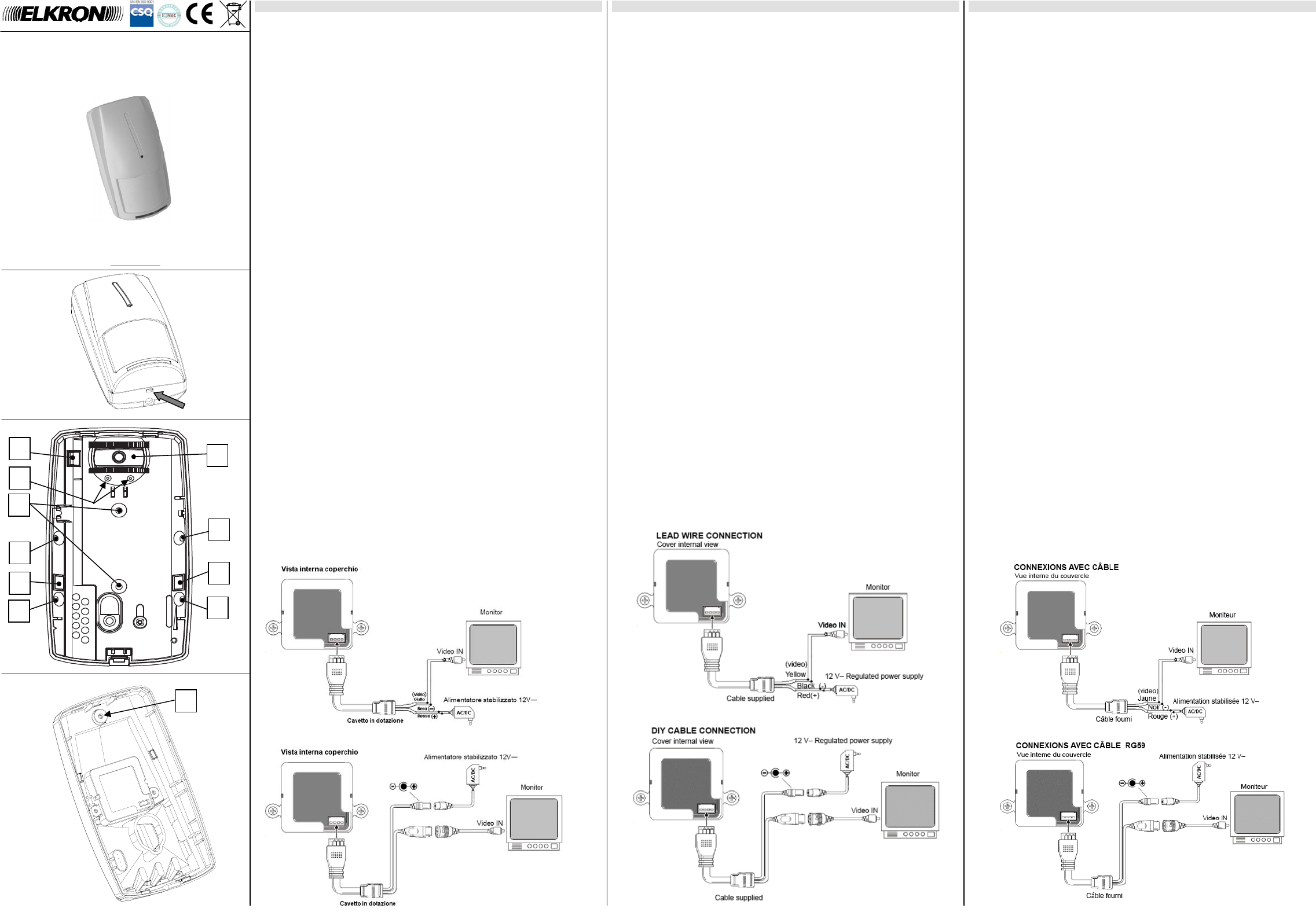
INDICAZIONI
•
A corredo viene for
in dotazione.
F
(vedi Fig.3)
.
•
Nel caso di impiego della conne
sfondamento
B1
(Fig.2) per il pas
ENGLISH
MICROCAMERA TECHNICAL CHARACTERISTICS
Image device ..........................................................
Scanning syste .....................................................
Scanning frequen
Horizontal reso
Total pixels ..............................................................
Effective pixels
Signal-to-noise ratio ................................................
Minimum lighting
Synchronization sy
Gamma correction ...................................................
Video output ............................................................Ω)
Lens
Electronic 000 sec
Operating Temper ...........................................
Storage temperature ...............................................
Humidity
Power Supply ..........................................................
Consumption @ 1
External case dimen
Weight inclu
SAFETY MEASURES
•
It is advisable t
quality image. A
which it can damage the camer
•
It is recommended to
input impedanΩ . If t
command on the
•
Do not try to d
intervention, al
•
Do not orientate the c
or photo reflectin
•
Do not expose
and cause electronic sho
INSTALLATION
INSTALLATION WITHOUT BALL-JOINT
•
To remove the
•
A
= ARRA
•
B/B1
= KNOCK DOWN ARRANGEMENTS FOR CABLES PASSAGE
•
C
= ARRA
INSTALLATION WITH BALL-JOINT
It is available (
and internal ca
down provision
“D”
and mount the
finished, if y
the equipment, compl
"E".
INDICATIONS
•
A kit with a us
Use the provi
F
(see Fig. 3).
•
When using the
B1
(Fig. 2) for the passage of the cable supplied.
FRANÇAIS
CARACTÉRISTIQUES TECHNIQUES DE LA
Dispositif d’ima .................................................... 1/3" SONY Sup
Système de bala
Fréquence de bal NTS
Résolution hor 550 TV
Nombre total de NTSC : 811(H) x
Pixels effectifs .........................................................
Rapport signal bruit .................................................
Éclairage minimal ....................................................
Système de synchron ................................... Intern
Correction gamm
Sortie vidéo .............................................................Ω)
Objectif .................................................................... Pinhoe 78°
Obturateur électro NTSC:1/60 ~ 1/100 0
Température de fon ............................. -10 °C ~ +50°
Température de sto ....................................... -20 °C ~ +60 °C
Humidité .................................................................. Inféri
Alimentation 12 V— (±10 % )
Consommation @ 12 V— .......................................
Dimensions e 124 x 70 x 54
Poids avec câble ..................................................... Enviro
NORMES DE SÉCURITÉ
•
L’utilisation d’une
fonctionnement s
normalement, en absence
•
Il est conseillé
d’entrée vidéo égaleΩ. Dans le cas où le monite
impédance, la ré
commander une
•
Ne pas essa
l’utilisateur. Pour
•
Eviter de tourner la
la distorsion d
•
Ne pas expo
L’humidité peut
INSTALLATION
INSTALLATION SANS ROTULE
•
Pour déposer le code fermeture (
fixation (Fig. 1)
•
A
= PRÉPERÇAGES POUR LA FIXATION EN ANGLE
•
B/B1
= PRÉPERÇAGES À PERFORATION POUR LE PASSAGE DES CÂBLES
•
C
= PRÉPERÇAGES POUR LA FIXATION SUR UNE SURFACE PLANE
INSTALLATION AVEC ROTULE
En option, on di
antimanipulation (KT
instructions sp
“D”
et assembler la r
comme indiqué da
fois l’orientat
logem
E
».
INDICATIONS
•
Si on souhaite fi
F
(voir Fig. 3)
.
•
Dans le cas
B1
(Fig. 2) pour le passage du câble fourni.
DS80TC5F-001 LBT8
Fig.1
Fig. 2
F
Fig. 3