EL-2645 / PI Wireless Motion PIR Detector Standard & Petimmune – Funkbewegungsmelder Standard & Haustierimmun - Détecteur de mouvement sans fil PIR Standard & Petimmune - Draadloze PIR Detector Standard & Petimmune
5IN1561
International Headquarters:
Electronics Line 3000 Ltd.
14 Hachoma St., 75655
Rishon Le Zion, Israel
Tel: (+972-3) 963-7777
Fax: (+972-3) 961-6584
All data is subject to change without prior notice techniques
In no event shall Electronics Line be liable for an amount in excess of EL3K’s original selling price of this product, for any loss or damage
whether direct, indirect, incidental, consequential or otherwise arising out of any failure of the product.
Hereby, Electronics Line declares that this sensor/transmitter is in compliance with the essential requirements and other relevant provisions
of Directive 1999/5/EC.
06/2011 5IN1561
The EL-2645 / PI is a Wireless Motion PIR
Detector designed for use with Electronics Line
supervised wireless range of receivers.
Location of Detector
Consider the following before mounting the
detector:
Select a location from which the pattern of
the detector is most likely to be crossed
by a burglar, should there be a break in.
Do not place bulky objects in front of the
detector.
Avoid a location that comes in direct
contact with radiators, heating/cooling
ducts or air conditioners.
Do not place the detector in front of
windows subject to direct sunlight or
drafts.
Installation Instructions
1. Open the housing by removing the front
cover. To do so, insert a screwdriver in
the release slot (located at the bottom of
the detector between the front and back
cover). Turn the screwdriver 90º to
release the cover.
2. Remove the PCB by turning counter-
clockwise and removing the 'PCB Screw'.
Note: Do not touch the face of the PYRO
sensor.
3. Apply battery power by removing the
isolator that separates the battery from the
contacts on the battery holder.
4.Set the receiver to Registration mode and
cause Tamper or Alarm transmission. Wait for
the receiver to indicate that the transmitter has
been registered successfully. Write the
number of the zone and the transmitter
number (if applicable) on the sticker provided.
Affix the sticker inside the front cover for future
reference.
Note: Alternatively, the Detector can be
registered to the receiver by manually
entering the transmitter's serial
number.
5.Choose an appropriate mounting height from
2.2 –2.5 and test the transmitter from the exact
mounting position before permanently mounting
the unit.
Note: If you choose mounting height other
than recommended (which is not
advised), pleaseperform a walk test to
check the lens coverage. The
recommended mounting height is the
best in terms of detection area.
6. Knock out the mounting holes and attach
the base to the wall.
7. If using the rear tamper switch, insert a
screw into the rear tamper mounting hole
located in the center of the back cover –
see Figure 3. When the detector is
removed from the wall, the screw causes
the tamper release to break away from the
back cover and the rear tamper switch is
released.
8. Mount the PCB on the base cover and
replace the PCB Screw.
9. Replace the front cover.
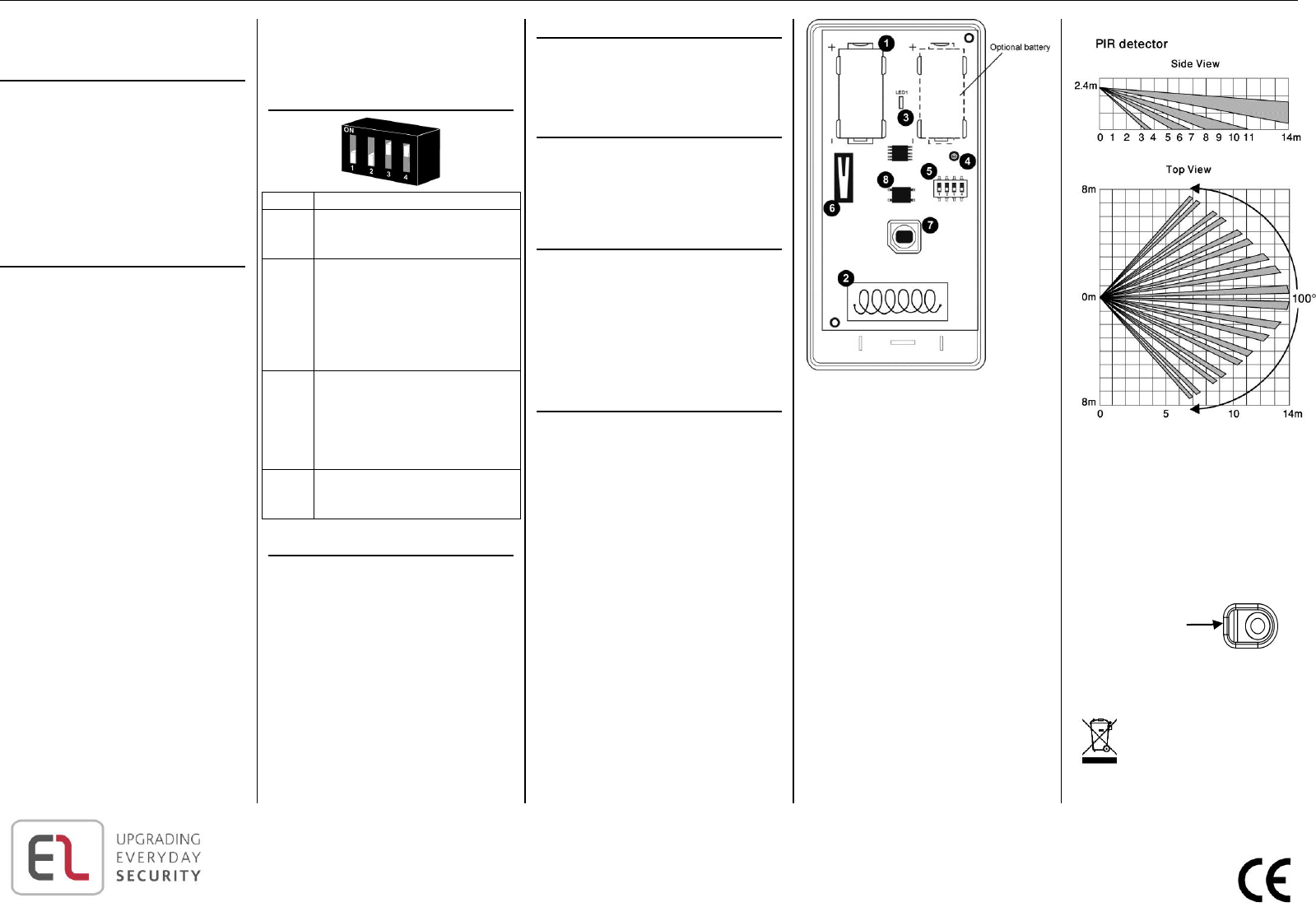
DIP Switches Settings
Switch
1
PIR sensitivity
* Off: Low
On: High
2
Operation mode:
* Off: Normal mode – Every 3 minutes.
After each detection the sensor initiates
a three-minute delay during which
alarm transmissions will not be sent
On: Walk Test mode. An alarm
transmission is sent after each
detection
3
Supervision Time:
Off: As supervision message will be
sent to the alarm panel every 15
minutes
* On: As supervision message will be
sent to the alarm panel every 65
minutes
4
LED
Off: LED disabled
* On: LED enabled
*=Default
Operation Modes
Warm-up Time: The detector will need to warm up
for the first 90 seconds after applying power.
Walk Test Mode: A walk test is performed in order
to determine the lens coverage pattern of the
detector –see Figure 2. Walk Test mode cancels
the delay time between detections, enabling you to
perform an efficient walk test.
To walk test the detector:
1. Set DIP 2 to ON.
2. Walk across the scope of the detector
according to the detection pattern
selected.
3.Confirm that the LED activates and
deactivates accordingly. Wait for ten
seconds after each detection before
continuing the test.
4. After completing the walk test. Set DIP-
2 to OFF.
LED Indication
The LED indicator is lit every time a transmission
is made. To enable/disable LED indication, refer to
DIP Switch Setting section for the appropriate DIP-
switch setting.
Note: The LED should only be disabled after
successfully walk testing the detector.
Changing Lenses
To change a lens, release the cavity seal using a
small screwdriver and fix the new lens into place
with the smooth side facing outwards. Verify that
the word TOP is located at the top of the lens
(alternatively a notch may appear on the bottom
edge of the lens) before snapping the cavity seal
back into place.
Battery Replacement
In case of a low battery (2.5 V and below), the
sensor low battery condition is reported to the
Control System and low battery message is
displayed
To replace a battery: Open the housing by
removing the front cover (see Installation
Instructions), replace the battery, and close the
front cover.
Note:Close the front cover immediately after
each battery replacement.
Technical Specifications
Frequency: 868.35, 433.92 MHz
Power: 3.6V ½ AA Lithium Battery
Caution: Fire, explosion and severe burn hazard!
Do not recharge, disassemble or heat above 100°C.
Current Consumption: 30mA (transmission), 8µA
(standby)
Pyroelectric Sensor: Dual Element
Maximum Coverage: 14 x 14m
Adaptive Temperature Compensation
RFI Immunity: According to EN 50130-4
Operating Temperature: -10 - 40°C
Fire Protection: ABS Plastic Housing
Dimensions: 110 x 60 x 45mm
Figure 1: PCB
1.Battery Holder
2.Antenna
3.LED Indicator
4.PCB Screw
5.DIP Switch
6.Tamper Switch
7.Pyro Sensor
8.Back Tamper
Figure 2: Lens Coverage
Note:The diagram shows the coverage
pattern for the detector fitted with a standard
lens of EL2645.
EL2645-PI has limited detection at the ground
to ignore animals
Rear tamper mounting
hole
Hulp nodig? Stel uw vraag in het forum
Misbruik melden
Gebruikershandleiding.com neemt misbruik van zijn services uitermate serieus. U kunt hieronder aangeven waarom deze vraag ongepast is. Wij controleren de vraag en zonodig wordt deze verwijderd.
Product:
Spelregels forum
Om tot zinvolle vragen te komen hanteren wij de volgende spelregels:
lees eerst de handleiding door;
controleer of uw vraag al eerder door iemand anders is gesteld;
probeer uw vraag zo duidelijk mogelijk te stellen;
heeft u een probleem en al geprobeerd om dit op te lossen, vermeld dit erbij aub;
heeft u een oplossing gekregen van een bezoeker dan horen wij dat graag in dit forum;
wilt u een reactie geven op een vraag of antwoord, gebruik dan niet dit formulier maar klik op de knop 'reageer op deze vraag';
uw vraag wordt direct op de website gezet; vermijd daarom persoonlijke gegevens in te vullen;
Belangrijk! Als er een antwoord wordt gegeven op uw vraag, dan is het voor de gever van het antwoord nuttig om te weten als u er wel (of niet) mee geholpen bent! Wij vragen u dus ook te reageren op een antwoord.
Belangrijk! Antwoorden worden ook per e-mail naar abonnees gestuurd. Laat uw emailadres achter op deze site, zodat u op de hoogte blijft. U krijgt dan ook andere vragen en antwoorden te zien.
Abonneren
Abonneer u voor het ontvangen van emails voor uw Electronics Line EL-2645 bij:
nieuwe vragen en antwoorden
nieuwe handleidingen
U ontvangt een email met instructies om u voor één of beide opties in te schrijven.
Ontvang uw handleiding per email
Vul uw emailadres in en ontvang de handleiding van Electronics Line EL-2645 in de taal/talen: Engels als bijlage per email.
De handleiding is 0,27 mb groot.
U ontvangt de handleiding per email binnen enkele minuten. Als u geen email heeft ontvangen, dan heeft u waarschijnlijk een verkeerd emailadres ingevuld of is uw mailbox te vol. Daarnaast kan het zijn dat uw internetprovider een maximum heeft aan de grootte per email. Omdat hier een handleiding wordt meegestuurd, kan het voorkomen dat de email groter is dan toegestaan bij uw provider.
Andere handleiding(en) van Electronics Line EL-2645
Uw handleiding is per email verstuurd. Controleer uw email
Als u niet binnen een kwartier uw email met handleiding ontvangen heeft, kan het zijn dat u een verkeerd emailadres heeft ingevuld of dat uw emailprovider een maximum grootte per email heeft ingesteld die kleiner is dan de grootte van de handleiding.
Er is een email naar u verstuurd om uw inschrijving definitief te maken.
Controleer uw email en volg de aanwijzingen op om uw inschrijving definitief te maken
U heeft geen emailadres opgegeven
Als u de handleiding per email wilt ontvangen, vul dan een geldig emailadres in.
Uw vraag is op deze pagina toegevoegd
Wilt u een email ontvangen bij een antwoord en/of nieuwe vragen? Vul dan hier uw emailadres in.