1. Applications
The controller is suitable for universal use,
e.g. for:
Floor direct, floor storage or open area
heating systems, swimming pool control, air
conditioning.
2.. Function
The controller is suitable for:
– heating
– cooling
a) Heating
UU
(Terminal -5)
If the temperature measured by the sen-
sor (actual value) is below the setpoint,
the controller is switched ON (relay picks
up).
If the temperature measured is above the
setpoint, the controller is switched OFF
(relay in de-energized position).
b) Cooling
PP
(Terminal -4)
If the temperature measured by the sen-
sor (actual value) is below the setpoint,
the controller is switched OFF (relay de-
energized).
If the temperature measured exceeds the
setpoint, the controller is switched ON
(relay picks up).
c) Hyseresis
Apart from the setpoint, the temperature
at which the controller switches over
depends also on the hysteresis adjusted
(switching differential), see Fig. 1. It can be
changed by means of the adjuster “hys-
teresis.“
d) Temperature setback 9:
(lowered setpoint) is effected by closing a
e
xternal-floating contact between termi-
nal 10-11, e.g. by means of an external
timer.
The green indicating lamp is lighted when
the relay is in on state.
The red indicating lamp warns of sensor
failure.
In the event of sensor failure, controller is
switched ON. This state is maintained until
the fault has been remedied. (Another variant
is available which will be in off state if a sen-
sor failure occurs).
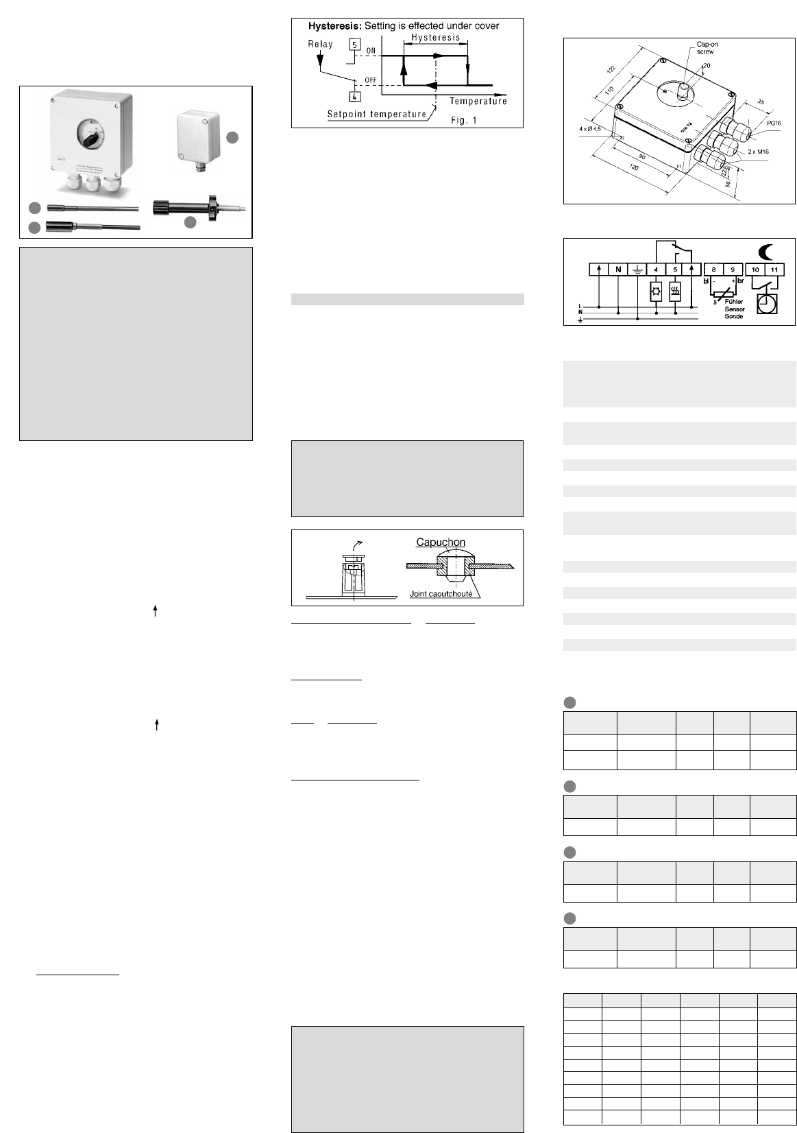
3. Installation / Connection
Fix base of housing by means of the 4 holes
provided to a suitable surface. Enter cable for
power supply and load through the M 16
screwed glands. Enter cable for
s-switching contact and sensor through the
PG-16 screwed gland. Cut out s-cable
opening. Firmly tighten up screwed glands;
tightening torque is 25 Nm.
Tightly seal unused screwed glands using
suitable material.
Modifikation for internal temperature setting
Proceed as follows:
1. Remove cover by taking out 4 screws
2. Lever out cap at top of adjusting knob.
See Fig 2
3. Slacken screw and pull off adjusting knob
4. Push spindle down into the interior
5. Firmly press the closure plug supplied into
the hole from the outside (see Fig. 3)
6. Re-place cover.
Cab
le for sensor and
s
-contact:
Use screened cables where leads are installed
in cable ducts or where they are run in parallel
with power cables for some distance.
For sensor
s:
May be extended to a maximum of 100 m
with 1.5 mm
2
conductor area.
For
s
-contact:
May be extended to a maximum of 10 m with
1.5 mm
2
conductor area.
Cable diameter: 8.6 mm ±0.3 mm.
Installation of sensor
s:
When installing the sensor, make sure that
satisfactory contact exists with the heat
source. The sensor should be able to follow
the temperature changes in the medium to be
controlled.
When installing the standard type of sensor
in liquid media or in areas where access is
difficult, it is absolutely necessary to provide
a protective tube (to facilitate replacement).
A pipe-mounted sensor should contact the
pipe as fully as possible.
In the case of in-air sensors, care should be
taken to ensure that the slot openings are
positioned in the direction of the air flow.
For electric connection, refer to the circuit
diagram provided inside the controller. All
leads to the controller must be fixed in place.
Attention 3!
The timer contact must be floating (basic
insulation); parallel connection of sever-
al timer contacts is not permissible.
Never apply mains voltage to a floating
timer contact (this will cause destruction of
the controller).
Attention 2!
In order to qualify for degree of protec-
tion class IP 65, it is necessary that the
closure plug should be pressed in solid-
ly with the rubber gasket.
4. Drawing
5. Wiring diagram
6. Technical data:
Order No. UTR 20 ( –40°C… 20°C)
UTR 60 ( 0°C… 60°C)
UTR 100 ( 40°C…100 °C)
UTR 160 ( 100°C…160°C)
EDP No.: 0524 72 14 x xxx
Operating voltage: 230 V AC (207… 244 V)
48 V… 62 Hz
Power consumption: ≤4 VA
Operating temperature: –20°C …50°C
Storage temperature: –40°C…70°C
Controller type: ON/OFF
Switching contact: Relay 1 x c/o contact, floating*
Switching current: ≤16 A cos ϕ = 1
(250 VAC): ≤ 4 A cos ϕ = 0.6
Hysteresis: ±0.5…± 5K (T ≤100 °C)
±0.5…±10 K (T >100°C)
Temperature setbacks: Approx. 5 K fixed
Type of sensor: PTC (KTY 83-110)
Protection class: II (see Attention 1)
Degree of protection: IP 65
Cable entry: Screwed glands: 2 x M 16; 1 x PG 16
Ordering No. PG 16: 000 193829 000
Weight: Approx. 440 g
*Also for switching safety extra-low voltage (SELV)
Technical data of sensors:
Operating Instructions
Electronic Temperature Controller
Type UTR-524 72
Attention 1!
The separately mounted unit must not be
opened except by authorised persons, and
this should not be attempted unless it is
isolated from the power supply. For the con-
nections refer to the circuit diagram provid-
ed inside the cover. It is mandatory in all
work on the unit to observe the current
safety regulations of the VDE, or its nation-
al equivalent, and those of the local power
supply companies.
In order to qualify for protection class II, it is
necessary to comply with the guidelines of
VDE 0100, or national equivalent standards.
Ordering No.
Ambient
temperature
Cable
lenght
Protection
class
Time con-
stant approx
F 897 001
–
40…80°C none IP 65 180 s
Ordering No.
Ambient
temperature
Cable
lenght
Protection
class
Time con-
stant approx
F 893 002
–
40…100°C 1.5m IP 30 10 s
Ordering No.
Ambient
temperature
Cable
lenght
Protection
class
Time con-
stant approx
F 892 002
–
40…120°C 1.5m IP 67 60 s
Pipe-mounted sensors:
Ordering No.
Ambient
temperature
Cable
lenght
Protection
class
Time con-
stant approx
F 894 002
F 891 000
–
50…175°C
–
5… 70°C
1.5m
4.0 m
IP 67
IP 67
30 s
30 s
Standard sensor:
Air-monitoring sensors:
Outdoor sensors:
C Ohm C Ohm C Ohm
-55 500 25 1000 110 1774
-50 525 30 1039 120 1882
-40 577 40 1118 125 1937
-30 632 50 1202 130 1993
-20 691 60 1288 140 2107
-10 754 70 1379 150 2225
0 820 80 1472 160 2346
10 889 90 1569 170 2471
20 962 100 1670 175 2535
Sensor characteristics: (for all types):
Specification subject to change without prior notice
B
D
A
B
C
D
C
Fig. 3Fig. 2
A