1. Applications
This electronic temperature controller is designed for
controlling the room temperature in conjunction with:
• heating systems e.g. hot-water heaters, convector hea-
ters or floor heating
• electric convector heaters, ceiling and storage heating
• night storage heaters
• circulation pumps
Features
• Nighttime set-back, input for external clock
• Indicator lamps for "controller calls for heat" and for
set-back operation
• 2-pole mains switch
• Mounting in 60mm flush-type box
2. Description of functions
2.1 Functions
The room temperature is measured by the integrated
sensor and is set via the outer dial.
The scale of *…6 corresponds to 5…30 °C.
Lamps
Red: Controller calls for heat
Green: Set-back mode is activated
2.2 Functions of the set-back input TA
The TA input is used to set the thermostat into the ener-
gy saving mode (by using an external timer).
In this mode, the room temperature will be reduced by
3° or 5° (depending on jumper J2).
2.3 Selecting the set-back temperature
By means of the J2 jumper it is possible to select 3° or 5°.
J2 closed* set-back by 5°C
J2 open set-back by 3°C
* = factory pre-set
The temperature set externally via the dial is reduced by
this value.
2.4 Remote sensor
For measuring the room temperature a remote sensor
can be used instead of the internal one.
If the remote sensor is connected, the internal one
automatically will be disabled.
Caution-1!
The device may only be opened and installed ac-
cording to the circuit diagram on the device or these
instructions by a qualified electrician. The existing
safety regulations must be observed.
In order to comply with safety class II, the necessary
installation steps must be taken.
This independently mountable electronic device is
designed for controlling the temperature in dry and
enclosed rooms only under normal conditions.
The device confirms to EN 60730, it works according
operating principle 1C
468 931 003 309-1
╞
Mounting and
Operating Instructions
Electronic room temperature controller
with set-back input
RTR R2A, 517 81 41…
2.5 Function of the lamps
Function Lamp green Lamp red
Heating is on on
Set-back mode on
external sensor failure blink blink
2.6 Master Reset
In case of unexpected behaviour of the controller
Master Reset should be carried out by performing the
following steps:
• Note the state of Jumper 2
• Switch off power supply
• Change state of J2
• Switch on power
• Switch off power
• Set the original state of J2
• Switch on power.
• Now the internal sensor is active.
3. Mounting / Commissioning
The controller should be mounted at a point in the
room which:
• can be easily accessed
• is free of curtains, cabinets, shelves, etc.
• allows free air circulation
• is not exposed to direct sunlight
• is not draughty (when doors or windows are opened)
• is not directly influenced by the source of heat/cold
• is not located on an outer wall
• is approx. 1.5 m above the floor.
Electrical connection
Perform the steps described below:
• Pull off the temperature dial
• Release the fixing screw
• Remove the upper part of the casing
• Connect acc. to circuit diagram (see bottom of casing)
Remote sensor F 193720 or F 190021
Do not install the sensor close to mains cables. In other
cases a shilded cable has to be used.
The sensor can be extended to max. 50 m by means of
a cable suitable for mains voltage.
Caution! Sensor leads carry mains voltage (230 V).
4. Technical data
Order designation RTR R2A, R2A/50
EDP No.: 517 8141…
Temperature setting range:*…6 (5…30ºC)
Indicator lamp red Controller calls for heat
green Set-back temperature
Power switch 2-pole
Supply voltage 230 V AC (195…253 V)
50 Hz
Output Relay make contact
Switching current: 100 mA…16 A cosϕ = 1;
100 mA… 4 A cosϕ = 0.6
Control algorithm Proportional controller
(similar to continuous
through PWM)
Switching temperature
differential ~0,5°C
Temperature sensor: internal
Remote sensor Type F 193720 or F 190021
(can be extended to 50 m)
Temperature set-back 3 K or 5 K selectable
via external timer
Range limitation inside the dial
Degree of protection
of casing IP30
Safety class II (see Caution-1)
Degree of pollution 2
Software class A
Calculation impulse voltage 2,5 kV
Temperature for the
Ball compression test 75°C
Voltage and Current for
the for purposes of
interference measurements 230 V, 0.1A
Ambient temperature 0…40ºC
Storage temperature –25…70ºC
Weight 90 g
Caution! De-energize the electric circuit first
Sensor characteristics
10°C 66.8 kΩ 30°C 26.3 kΩ
20°C 41.3 kΩ 40°C 17.0 kΩ
25°C 33 kΩ 50°C 11.3 kΩ
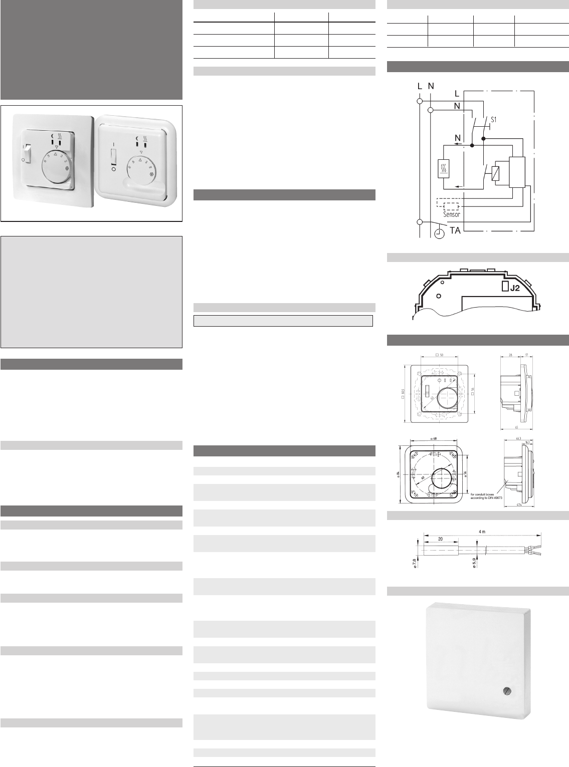
5. Circuit diagram
Position of the jumpers
6. Dimensions
Remote sensor F 193720 as accessory
Remote sensor F 190021 as accessory
cover one partscover two parts,
50 x 50 mm