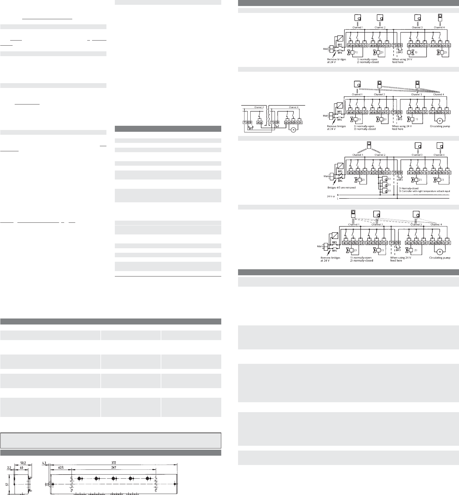
8. Wiring diagrams and examples
Fig. 1
Each transmitter
controls a switching
output for heating ON/OFF.
No master/slave.
Graphical representation of
230 V actuators.
Fig. 2
Each transmitter controls a switching output for heating ON/ OFF. Additional pump logic. No master/slave.
Graphical representation of 230V actuators/pump.
Extension of pump logic
to two receiving modules
Fig. 3
Each master controls one switching
output (channel 1) and an associated time
switch output (channel 2) for temperature
setback of other controllers.
Slaves on channels 3, 4.
Graphical representation
of 24 V actuators
Fig. 4
One master (channel 1) with 2 slaves (channel 2, 3).
Additional pump logic (channel 4).
A third slave can be programmed at
channel 4. Connect a valve instead
of a pump.
Graphical representation
230 V actuators
9. Brief operating instructions for the INSTAT 868-a4 radio frequency receiver
Deleting the radio links 3.6 • Press the channel 1 button + the reset button simultaneously
• Release the reset button, then the channel 1 button
Testing the radio distance 3.7 • Set transmitter to Learning mode
• Press the channel 2 button + reset button simultaneously
• Release the reset button, then the channel 2 button
• Channel 2 signal lamp lights up
• Signal tone + relay are operating in the switching mode (brief ON - extended OFF)
• When the switching mode ceases to operate, the radio distance is exceeded
• Press the reset button for termination
• Transmitter: switch off Learning mode
Establishing the radio link 5.1 • Set transmitter to Learning mode
Function or 3.1 • Briefly press the channel button!
”Switching mode” • Signal lamp lights up + signal tone sounds
• When transmitter is identified, signal lamp + tone will stop
• Transmitter: switch off Learning mode - press the OK button
Function 3.2 • Channels 1, 2, 3 Switching mode - Channel 4 Pump logic
pump logic • Function is active, as long as channel 4 is not programmed
• Like function "Switching mode"
Function 3.3 • Set Transmitter to Lerning mode
• Briefly press channel 1 + 2 or channel 3 + 4 buttons
Switching and time switch output • Signal lamps light up + signal tone sounds
• When transmitter is identified, signal lamp extinguishes and signal tone ceases
to sound
• lower number = switching output (actuator)
• higher number = time switch output
• Transmitter: switch off Learning mode
Function 3.4 • Slaves follow master switching times
Master/slave • Assign master to channel 1, program slaves to following channels
Changing Heating/Cooling mode 3.5
Heating • Winter mode (as-delivered condition)
• Press the channel 4 + the reset button simultaneously
• Release the reset button, then the channel 4 button
Cooling • Summer mode
• Press the channel 3 button + the reset button simultaneously
• Release the reset button, then the channel 3 button
Displaying programmed channels 3.8 • Press the reset button – programmed channels will be briefly displayed
Valve test 5.2 • Press the channel button
• As long as the channel button is pressed, the output switches On
• Press the reset button within 10 sec. after releasing the channel button
Signal lamp - Fault messages 5.5
– Brief double flash • Double addressing - reprogramming the transmitter
– Brief single flash +
no signal tone • Brief losses of transmitter signal (1h up to 10 h)
with signal tone • Extended losses of transmitter signal (more than 10 h)
Output receives 30% of the manipulated variable (3 min. ON - 7 min. OFF)
press the reset button. This switches the relays to the OFF
status. When new actuating signals are received (possibly
after 10-20 min.), they will continue to work.
Any existing radio link will be maintained.
5.5 Faults
If faults occur, an alarm is triggered. In this case, the signal
lamp flashes
with varying duration, if necessary, a signal tone
sounds.
5.5.1 Double addressing
In this case the signal lamp flashes permanently two times
short one after the other. The signal sounds be cancelled by
re-learning one of the both transmitters. The output is
switched with 30% capacity (3 minutes ON, 7 minutes OFF).
5.5.2 Brief losses of the transmission signal
If the transmitter fails to receive an actuating signal within a
period of 1 and up to ~10 hours, the signal lamp shows a per-
manent one brief flash
. No signal tone sounds.
The output is switched with 30% of the manipulated variable
(3 min. ON, 7 min. OFF).
Upon the transmission signal recurring, the alarm automati-
cally ceases.
5.5.3 Longer losses of the transmission signal
If the transmitter has not received an actuating signal for
more than 10 hours, the signal lamp shows permanent one
short flash. The signal tone sounds.
The output is switched with 30% of the manipulated variable
(3 min. ON, 7 min. OFF).
Upon the transmission signal recurring, the alarm automati-
cally ceases.
Note:
• In the case of heating systems that are in stand-by mode
even in the summer, e.g. electric heaters, the valve protec-
tion (in the transmitter) must be switched off.
In the other case the output would be switched On for 3
minutes each day!
• The signal tone can be switched off permanently by remov-
ing bridge BR 1.
For all t
ypes of faults, the following a
pplies:
• Function – Switching mode – A fault at one output will not
affect the other outputs.
• Function – Pump logic – A pump keeps ON operating in the
alarm mode (already after one transmitter has failed).
• Function – Time switch output –: The faulty behaviour also
applies to the associated time switch output.
• Function – Master/Slave – In the case of the master failing,
the slaves are switched to comfort mode.
• A flashing signal lamp indicates the alarm status, not the
switching status of the output.
• After a power failure in the transmitter or in the receiver,
normal operation is resumed.
• Under unfavourable local conditions it is possible that the
radio link between the transmitter and the receiver is insuf-
ficient, for instance, if the receiver is installed in an inter-
ference-proof metal housing. Please check whether the sit-
uation improves when the transmitter is arranged in a dif-
ferent position. For checking the radio link, see Section 3.7.
Table 1: When the radio link does not work…
Check the following: Yes No
1. Receiver: Is signal lamp ‘Power’ lighting up? Continue with 2 Check power supply possibly the
unit is defective
2. Receiver: Is a channel 1…4 signal lamp flashing? Double addressing see Section 5.5.1 Continue with 5
Can the warning tone be heard? or transmission signal is missing
(possibly only after one hour) Continue with 3
3. Press the reset button Continue with 4 Transmitter not programmed
Are the required channel signal lamps lighting up briefly? Reprogram, see Section 5.1
See Item 3.8
4. Transmitter: Is the battery OK? Continue with 5 Insert new batteries
5. Transmitter: Adjust to 30°C. Is the relay switched on after Continue with 6 Relay was already switched on
~30 sec? (signal lamp lights up). . Continue with 6 or transmission
signal is missing, continue with 7
6. Transmitter: Adjust to 5 °C. Is the relay switched off Everything OK Transmitter signal is missing,
after ~30 s (signal lamp does not light up) continue with 7
7. Transmitter-receiver-actuator: Check wiring, if Everything OK Continue with 8, if necessary,
necessary, reprogram connection to radio receiver. check radio link distance,
see Section 3.7
Are Items 5 and 6 now successful? “Testing the radio link distance“
8. Reduce distance between receiver and transmitter Transmitter and receiver are Transmitter or radio receiver are
to ~2 m (not less). Are Items 5 and 6 working properly defective
now successful?
7. Dimensions (for INSTAT 868-a4 )
Base Unit Extension Unit
5.6 Troubleshooting
1. Valve does not open:
➜ Has it been properly wired up?
➜ Has the radio link been established? (see Section 5.1)
➜ See table 1 up from item 3.
➜ Press the reset button (see Section 5.4)!
2. The signal lamp for a radio channel flashes and possi-
bly a beeper is sounding
➜ For basic fault procedures, see Section 5.5
➜ Learning mode, valve test, radio range test have not
been interrupted (see Sections 5.1, 5.2, 3.7, 5.4)!
➜ Two transmitters are transmitting with the same ad-
dress; reprogram the associated radio link (see Sec-
tion 5.5.1)!
➜ No radio link, see Item 7 in the Table1 !
➜ One or more channels which are not in use are flashing.
These channels have lost their transmitter.
Proceed as described under Section 3.6 ‘Deleting the
radio link’. Re-lern needed links.
3. The channel 4 signal lamp lights up, although no
transmitter has been programmed.
• Channel 4 serves as a pump logic, see Section 3.2.
In the case of inexplicable faults it is recommended to press
the reset button on the receiver and, if necessary, on the
transmitter.
6. Technical data
Type INSTAT 868-a4
Article-No. 0536 40 140 …
Operating voltage 230 V (195…253 V) 50/60 Hz
Power consumption < 3 VA
Ambient temperature 0…+50°C
(without condensation)
Storage temperature –20…+60°C
Aerial Internal
Push-button: for programming 4
for reset 1
Lamps: for programming 4
for operating volt. 1
Load circuit: 4 changeover contacts,
6A cosϕ =1; 2A cosϕ = 0.6
**
24 ... 230 V AC volt free*
Number of actuators per contact:***
3 W each electrothermal
230 V 10*** max.
24 V 4*** max.
Double-pole insulation voltage
when bridges BR 4,5 are
opened 400 V* max.
Single-pole insulation voltage
when bridge BR 3 is opened 230 V* max.
Protection class of housing IP 40 / insulated
Software class A
Rated impulse voltage 2.5 KV
Brinell test temperature 75°C
Voltage and current for EMC 230 V, 6 A
emitted interference testing
Weight ~530 g
*) After complete removal of bridges BR 4, 5, a creepage distance and clear-
ance of 8 mm between the operating voltage and the relay terminals is
guaranteed. The unit is therefore suitable for switching safety extra-low
voltage (SELV). After removal of bridge BR 3, the two switching units
(channels 1/2 against channels 3/4) show a 230 V basic insulation.
**) Total of all currents <= 10 A With a total of all currents of >2 A, install as
described under ”Switching a second voltage” (see Item 4, Installation).
***) A maximum of 10 x 4 = 40 (230 V) actuators or 4 x 4 = 16 (24 V) actuators
respectively can be controlled by an INSTAT 868-a4 at one time.
Four actuators can be mechanically connected to the six-point terminal. If
there are more actuators, provide external terminal points.
Note: In individual cases it may not be possible to establish a permanent radio link between radio transmitter and radio receiver. The rea-
son for this is not to be attributed to our radio control, but to the radio distance to be used. Therefore, we recommend checking its prop-
er functioning at the respective place of installation.