GB
ATTENTION
zz
The controller may only be opened by an ex-
pert and to be installed according to wiring dia-
gram inside cover. The current regulations for
safety at work have to be observed.
ÖÖ
Will be achieved by relevant installation
procedures (acc. to VDE 0100) and by cor-
rect mounting on smooth surface non-
conductive and non-flammable.
This controller which can be installed indepen-
dently is designed exclusively for regulating
the temperature indoors in dry and enclosed
rooms under normal environmental condi-
tions.The controller has radio interference
suppression acc. to VDE 0875 resp. EN 55014
and operates to efficiency 1 C.
1. Application
●
Electric Floor Heating Systems
●
Hot Water Floor Heating Systems
2. Operation
The controller recognizes the temperature via the ex-
ternal remote sensor.The controller switches on when
sensor temperature is below set temperature and it
switches off as soon as required room temperature
(set value) will be reached and rise.
The setting range 1...6 corresponds to temperature
10...60°C.
The controller can be switched ON and OFF by means
of the rocker switch.
The red LED indicates „calling for heat“
In case of sensor disconnection or shortcircuit the re-
lay will drop.
The variants with a tamper proof housing do not have a
mains ON/OFF switch, the temperature adjustment is
under the top cover.
3. Installation
a) Controller
– System to be wired free of voltage
– Pull off the adjusting knob
– Loosen the fixing screw
– Remove the cover
– Connection acc.to wiring diagram (inside cover)
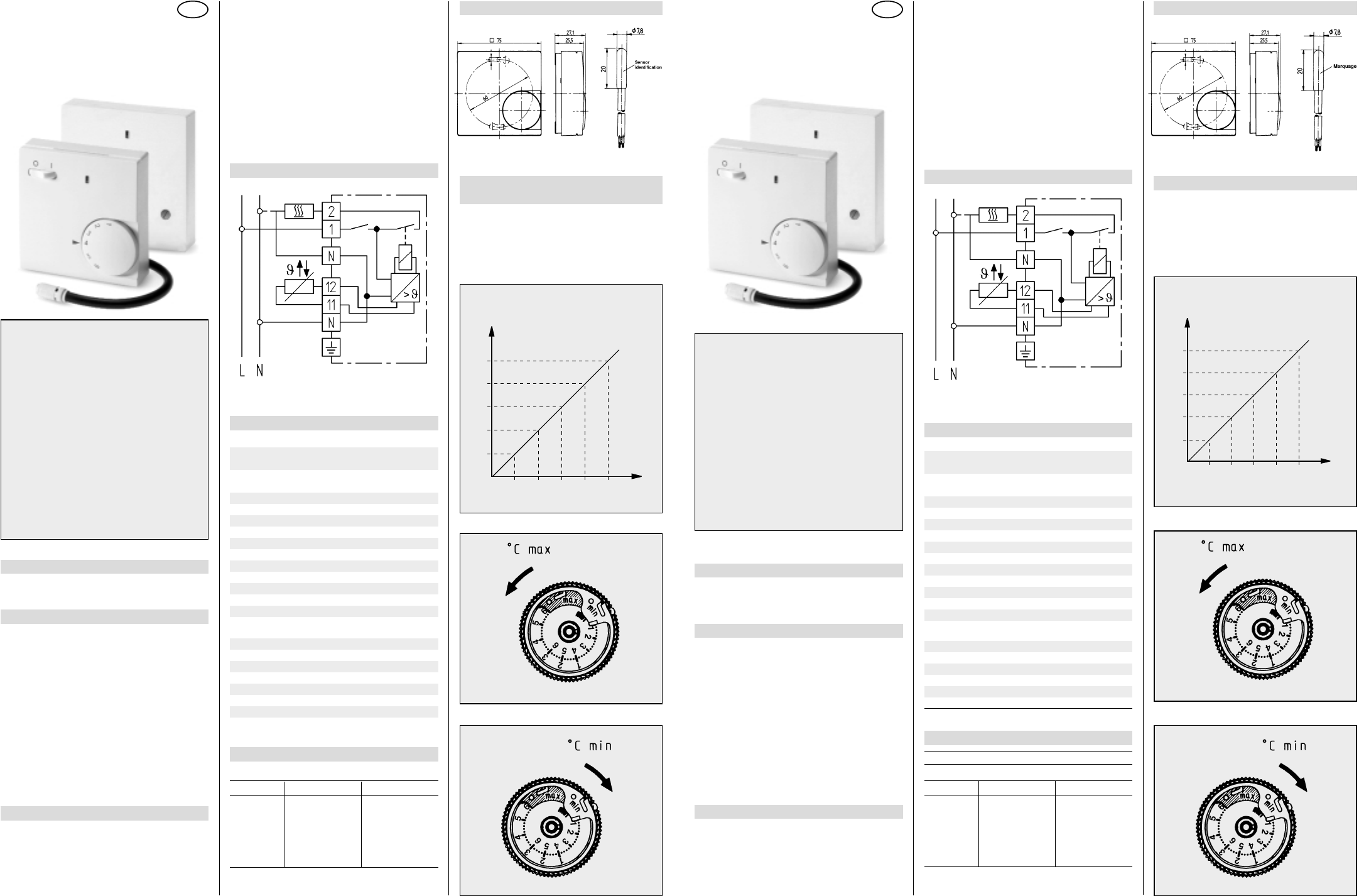
4.Wiring Diagram
For variants with a tamper proof housing the wiring
diagram is inside the top cover.
5.Technical Data
Controller
Article no. 515 1105…
Switching current 14 A (4 A cos ϕ = 0,6)
Article no. 515 1106…
Switching current 16 A (4 A cos ϕ = 0,6)
Operating voltage at 50 Hz 230 V AC (195 ... 253 V)
Temperature range 1...6 (corresponds to 10...60°C)
Switch mains ON/OFF
Indication LED calling for heat
Contact (Relay) 1 n/o (for „heating“)
Mode of regulation on - off
Switching differential approx. 1 K
Protection class of housing IP 30
Degree of safety II*
Operating temperature –20 ... +40°C
Storage temperature –20 ... +70°C
Remote Sensor
Full Ref. No. 000 193 720 000
Sensor identification white
Sensing element NTC
Sensor cable PVC (2x0,5 mm2)
Length of cable 4 m
Protection class IP 68
Ambient temperature –25 ... +70°C
* See point ”Attention“
b) Remote Sensor
Attention:
For more easy replacement sensor cable should
be put into a protection tube. The sensor cable
can be lengthened up to 50 m by using a standard
2-core cable for mains voltage and with a cross
section of 1,5 mm2. Close parallel routing along
high voltage cables or in cable ducts should be
avoided or otherwise a screened cable has to be
installed.
Attention:
In case of failure the sensor cable still can carry mains
voltage.
6. Dimensions
7. Limiting the
temperature range
Preset of controller to max.setting range at factory.
Inside of adjustable knob there are 2 setting rings
with a range of 1 to 6. For limiting the range, please
consider following diagram.
Characteristics of NTC resistor
Temperature range 10 .. .60°C
[kΩ][V]
10°C 66,8 3,7
20°C 41,3 3,4
30°C 26,3 2,9
40°C 17,1 2,5
50°C 11,3 2,0
60°C 7,5 1,5
Ohmic values only can be tested on disconnected sen-
sor cable
468931 002846-02
Installation and
Operating Instructions
Temperature Controller for
Floor Heating Systems
F
ATTENTION! z
Cet appareil doit être monté et branché selon
le schéma se trouvant dans le couvercle par
un professionnel et dans le respect des
règles de sécurité et des normes en vigueur.
Ö
Est réalisé par un montage sur une sur-
face plane, non conductrice et in inflam-
mable.
Ce thermostat sert à réguler la température
de pièces sèches et fermées dans un envi-
ronnement normal. Il est antiparasité selon
VDE 0875; EN 55014 en conformité avec la di-
rective 1C.
1. Domaines d’utilisation
●
Chauffage au sol électrique
●
Chauffage au sol par eau
2. Fonctionnement
La température est mesurée par la sonde à distance. Si
celle-ci est inférieure à la consigne, le thermostat en-
clenche le chauffage;si elle est supérieure, le chauffage
sera coupé.
La plage de réglage de 1…6 correspond à une tempéra-
ture de 10…60 °C.
L’interrupteur permet l’arrêt ou la mise en route du ther-
mostat.
La Led rouge signale la mise en route du chauffage.
En cas de coupure ou de court-circuit de la sonde, le
relais de sortie est désexcité.
Les variantes avec boitier étanche ne disposent pas de
contact marche/arrêt, le réglage de la température se fait
sous le couvercle.
3. Montage
a) Thermostat
– Mettre l’installation hors-tension
– Retirer la molette du thermostat
– Enlever la vis
– Retirer la couvercle
– Brancher selon le schéma (dans le couvercle du
boîtier)
4. Schéma de branchement
Les variantes avec boitier étanche disposent du
schéma de câblage à l’intérieur du couvercle.
5. Caractéristiques techniques
Thermostat
No. d’article 515 1105…
Intensité max 14 A (4 A à cos ϕ =0,6)
No. d’article 515 1106…
Intensité max 16 A (4 A à cos ϕ =0,6)
Tension à 50 Hz 230 V AC (195…253 V)
Plage de température 1…6 (= 10…60°C)
Interrupteur M/A
Voyant Led Chauffage allumé
Sortie relais 1 contact travail
Régulation Tout ou Rien
Hystérésys env. 1 K
Protection IP 30
Classe protection II*
Température ambiante: –20 … 40 °C
Température Stockage: –20 … 70 °C
Sonde
Référence: 000 193 720 000
Elément sensible CTN
Cable PVC (2 x 0,5 mm
2
)
Longueur 4 mètres
Protection IP 68
Température ambiante: –25 … 70 °C
* Voir point »Attention«
b) Sonde de température
Attention:
Pour faciliter un éventuel remplacement, placer la
sonde dans un conduit de protection
Le câble de sonde peut être prolongé jusqu’à
50 mètres avec un câble:
– de section 1,5 mm
2
– adapté à la tension secteur
Si le câble passe dans des goulottes de câbles ou est à
proximité de conducteurs de puissance, employer du
câble blindé.
Attention:
En cas de défaut, la sonde peut se trouver à la ten-
sion secteur!
6. Dimensions
7. Limitation de la plage de réglage
A la livraison, toute la plage est accessible.
A l’intérieur de la molette se trouvent 2 bagues, (l’une
pour la valeur max. l’autre pour la valeur min.) pouvant
être positionnées sur une plage de 1…6.
Se référer au diagramme suivant pour le réglage
Caractéristiques de la sonde
Couleur de la sonde: blanche
Température de la sonde 10 .. . 60°C
[kΩ][V]
10°C 66,8 3,7
20°C 41,3 3,4
30°C 26,3 2,9
40°C 17,1 2,5
50°C 11,3 2,0
60°C 7,5 1,5
les valeurs ohmiques ne peuvent être mesurées que
sonde débranchée!