38149
2
Verklein
Vergroot
Pagina terug
1/2
Pagina verder
N L 1 2 3 4
50 mm
minimum
clearance
40 mm
minimum
clearance
40 mm
minimum
clearance
70 mm
minimum
clearance
N L 1 2 3
230V AC 50Hz
Fused 3A
Common
heating
satisfied
or call for
cooling
Call for
heat
Vo
lt free contacts
N L 1 2 3 4
L
SCR
See
note
Switched live
from wiring
centre
Motorised valve
N
To boiler
and/or
pump
Radio signals
to SCR - no wirin
g
230V AC
fused 3A
N L 1 2 3 4
SCR
L -
N -
Digistat + RF
Digistat + RF
Radio signals
to SCR - no wirin
g
Switched
230V AC
fused 3A
,
Internal
boiler
electronic
s
External
controls
connections
TAMPER PROOFING (All Models)
To tamper proof the product i.e. prevent unauthorised adjustment of
the product set the Min and Max temperatures to the same desired
value.
FAULT DIAGNOSIS
(All Models)
If the display shows E1, the following faults could have occurred
1. Internal temperature sensor has failed.
2. Ambient temperature is outside product operating temperature range.
5
ºc
p
p I
H i
00
E S
E
I
E 2
E L
Y
C Y
F
i 0
ºc
i 5
ºc
3
ºc
2 4
ºc
9 0
ºc
6 0
ºc
4 0
ºc
3 0
ºc
2 0
ºc
7 0
ºc
L
p I
0 0
C Y
F
E S
E L
Y
S ET
i 5
ºc
S ET
2 2
ºc
BATTERY REPLACEMENT (All Models)
When the batteries are getting low (approx 30 days battery
life remaining) the battery symbol will flash in the display, it is
recommended to change the batteries during this period.
After approx 30 days, a continuous battery symbol only
will be
shown in the display and the unit will remain OFF.
How to replace the batteries
Remove the battery compartment by pinching the tabs and
withdrawing downwards. Replace the spent batteries with 2 x AA 1.5V
alkaline batteries ensuring correct orientation. Replace the battery
compartment pressing fully home.
RF PRODUCT ONLY
SCR RECEIVER (RF Model only)
SCR (Receiver) Normal Operating Mode
Once the ‘Wireless System’ has been commissioned, there should
be little need for any user interaction with the SCR.
During normal operation the red and green LEDs will occasionally
be on, these signify the following;
Green LED
The green LED will be on when there is a demand for heating, and
off when there is no demand.
Red LED
The red LED will flash for 7 seconds, approximately every 5
minutes. This denotes that a radio signal is being received from
the Digistat+RF unit.
Situations Requiring Attention
Red LED continually flashing
This denotes that the batteries in the Digistat+RF unit are
approaching the end of their life (see ‘battery replacement’).
Red LED continually on
This denotes that the SCR has been unable to receive a radio
signal from the Digistat+RF unit. This may be caused by the
batteries being dead (see ‘battery replacement’) or some
temporary interference with the radio signal.
To resend and test the signal, go to the Digistat+RF unit and open
the battery drawer, after a few seconds (the display will go blank)
close the battery drawer and then reset to your desired
temperature. If the radio signal has been successfully transmitted
and received, the red LED will flash for 7 seconds then go off.
If the red LED stays on, there may be some other fault that will
require the attention of a heating engineer/electrician.
Manual Overide
The heating can be manually switched on and off by using the
‘OVERRIDE’ button on the SCR in a fault situation, even though
the red LED will stay on until a satisfactory signal is reinstated.
Once the SCR receives a satisfactory signal again, it will
automatically reset itself for normal operation.
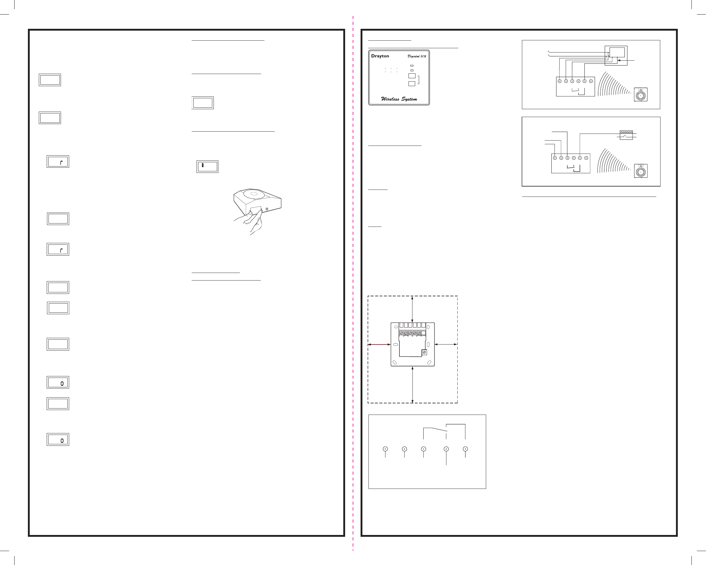
Combi boiler basic wiring layout
Zone control basic wiring layout
COMMISSIONING THE ‘WIRELESS SYSTEM’ (RF Models only)
Standard for all models
IMPORTANT: MULTIZONE INSTALLATIONS ONLY
If more than one ‘wireless system’ is fitted within the same property.
ie. for controlling 2 or more zones (multi-zone) it is essential that the
Digistat RF units are matched correctly to the relevant SCR. This is
easily achieved by commissioning each Digistat and SCR in turn.
1. Install (see installation instructions) and turn power on to the
SCR (receiver). If a separate programmer is fitted, ensure that it is
switched on. The red LED should come on.
2. Push the ‘override’ button on the SCR once. The green LED should
also come on. Check to see if the boiler and/or motorised valve
are working.
3. To enter ‘learn’ mode push the button marked 1 followed by 2
(OVERRIDE) and hold both depressed together. The red LED
should flash for 2 seconds and then go out signifying the SCR is in
learn mode. Release both buttons.
4. The
red and green LED’s should both now be on.
5. Take the Digistat RF and hold it within sight of the SCR (no closer
than one metre).
6. Insert the batteries into the holder and slide them into the Digistat
RF until the drawer clicks into place.
7. The Digistat RF should now display the actual room temperat
ure.
If the unit has been stored in a cold place
, it may take time to
warm up.
8. As soon as the battery compartment is slid back into place, the
red LED on the SCR should flash for 7 seconds and then go out.
The green LED may be on or off depending on th
e room
temperature at the time of commissioning.
9. If the red LED remains on, slide down the battery drawer on the
Digistat RF, check the battery positions are correct, and once
the
display
has faded, repeat steps 6 to 8.
10. Increase the ‘SET’ temperat
ure on the Digistat RF by rotating the
dial clockwise until a flame symbol appears, in the left hand
segment of the display.
11. The red LED on the SCR should flash for 7 seconds. This confirms
that the radio signal is being sent and received. After 7 seconds
the red LED should go out and t
he green one come on.
12. Check to confirm that the boiler and/or motorised valves are
working.
13. De
crease the ‘SET’ temperature on the Digistat RF by rotating the
dial anticlockwise until the fla
me symbol disappears.
14. The red LED on the SCR should flash for 7 seconds. After 7
seconds both the red and green LEDs should go out. Check that
the boiler and/or motorised valve have powered
down.
15. Place the Digistat RF in the chosen operating position, (see Digistat
RF location section) and repeat steps 10 to 14. Once you have
confirmed the system operates correctly, fit and secure the
Digistat
RF to the wall (see installation instructions).
During normal operation the red LED on the SCR will flash for 7
seconds each time a radio signal is received from the Digistat RF. This
will occur approximately every 5 minutes.
The green LED on the SCR denotes a call of heat (ON).
Once the system has been successfully commissioned, buttons 1
and 2 on the SCR should not be pressed simultaneously, unless a
replacement Digistat RF or SCR is fitted.
RF PRODUCT ONLY
INSTALLATION OF SCR
(RF Models only)
HEATING ON
RECEIVE / ALARM
OVERRIDE
LEARN
MODE
If you do not have the knowledge to install the SCR safely then you
must arrange for a competent electrician to install it for you. Wiring
must conform to the current IEE regulations.
Prior to commencing the installation you must ensure the mains supply
is switched off.
Installation Instructions
Read all installation and commissioning ins
tructions before
proceeding.
Do not switch on until ready to commission.
The system wiring must be able to be fully disconnected from the
mains supply by a switch incorporated in the fixed wiring having a
contact separation of at least 3mm on both poles. Fused at 3A.
Location
The Digistat SCR (receiver) should be mounted in a convenient
position, close to the combi boiler or central heating system wiring
centre. (Care should be taken not to mount the SCR in a position
where it is surrounded by metal objects or mains voltage cable, as this
may interfere with the radio signal).
Fixing (minimum wall plate clearances shown)
1. Loosen the securing screws, remove the wallplate, and if surface
wiring is to be used, snap out the cable entry strip on the bottom
edge of the wallplate with a pair of pli
ers.
2. Fix the wallplate, terminals at the top, either direct onto the flat
wall using wall plugs and no 6 x1” wood screws or on a flush
mounting single conduit box using M3.5 x 14 screws. Minimum
wallplate clearances are shown.
3. Complete the wiring to the SCR wallplate in accordance with the
relevant diagram, to com
ply with current IEE regulations.
4. Place th
e SCR onto the wallplate and tighten the securing screws.
SCR wallplate clearances
Electrical
This product is double insulated and does not require an earth
connection. The SCR should be wired to the combi boiler or central
heating wiring using the correct type of cable or flex. The SCR should
be wired in to replace hard wired room or programmable thermostats
shown on the system or boiler wiring diagrams. Always check other
manufacturers instructions for compatibility.
To cancel the Preset Mode & return to normal operation
You can either,
1. If you want to return to your previous setpoint (before you entered
the Preset mode) then press the ‘SET’ button. The Preset mode will
be cancelled and the product will return to normal operation and the
display will show the current room temperature as shown,
5
ºc
p
p I
H i
00
E S
E
I
E 2
E L
Y
C Y
F
i 0
ºc
i 5
ºc
3
ºc
2 4
ºc
9 0
ºc
6 0
ºc
4 0
ºc
3 0
ºc
2 0
ºc
7 0
ºc
L
p I
0 0
C Y
F
E S
E L
Y
S ET
i 5
ºc
S ET
2 2
ºc
2. If you want to set a new setpoint, just rotate the dial until your
required setpoint is shown on the display. After a couple of seconds
the display will change to show the current room temperature as
shown,
5
ºc
p
p I
H i
00
E S
E
I
E 2
E L
Y
C Y
F
i 0
ºc
i 5
ºc
3
ºc
2 4
ºc
9 0
ºc
6 0
ºc
4 0
ºc
3 0
ºc
2 0
ºc
7 0
ºc
L
p I
0 0
C Y
F
E S
E L
Y
S ET
i 5
ºc
S ET
2 2
ºc
To change the user adjustable settings
To enter the ‘User’ menu, press and hold the ‘Set’ button for
more than 5 but less than 10 seconds – the display will show ‘Pr’
(Preset temperature setting) as shown,
5
ºc
p
p I
H i
00
E S
E
I
E 2
E L
Y
C Y
F
i 0
ºc
i 5
ºc
3
ºc
2 4
ºc
9 0
ºc
6 0
ºc
4 0
ºc
3 0
ºc
2 0
ºc
7 0
ºc
L
p I
0 0
C Y
F
E S
E L
Y
S ET
i 5
ºc
S ET
2 2
ºc
If the dial is turned clockwise one click then ‘HI’ (Maximum
temperature setting) will be displayed and if turned one more click
clockwise then ‘Lo’ (Minimum temperature setting) will be displayed.
Changing the Preset Temperature
To adjust the ‘Preset’ temperature enter the user menu as
described above, then rotate the dial until ‘Pr’ is shown, press the
set button and the display will show the current Preset setting.
5
ºc
p
p I
H i
00
E S
E
I
E 2
E L
Y
C Y
F
i 0
ºc
i 5
ºc
3
ºc
2 4
ºc
9 0
ºc
6 0
ºc
4 0
ºc
3 0
ºc
2 0
ºc
7 0
ºc
L
p I
0 0
C Y
F
E S
E L
Y
S ET
i 5
ºc
S ET
2 2
ºc
Rotate the dial clockwise to increase the Preset temperature
& anti-clockwise to reduce the Preset temperature. Press the
‘Set’ button to confirm and ‘Pr’ will be displayed.
5
ºc
p
p I
H i
00
E S
E
I
E 2
E L
Y
C Y
F
i 0
ºc
i 5
ºc
3
ºc
2 4
ºc
9 0
ºc
6 0
ºc
4 0
ºc
3 0
ºc
2 0
ºc
7 0
ºc
L
p I
0 0
C Y
F
E S
E L
Y
S ET
i 5
ºc
S ET
2 2
ºc
Changing the Maximum Temperature Setting
To adjust the maximum temperature setting enter the user
menu as described above, then rotate the dial clockwise until ‘HI’
is showing.
5
ºc
p
p I
H i
00
E S
E
I
E 2
E L
Y
C Y
F
i 0
ºc
i 5
ºc
3
ºc
2 4
ºc
9 0
ºc
6 0
ºc
4 0
ºc
3 0
ºc
2 0
ºc
7 0
ºc
L
p I
0 0
C Y
F
E S
E L
Y
S ET
i 5
ºc
S ET
2 2
ºc
Then press the ‘Set’ button, the current setting is shown.
5
ºc
p
p I
H i
00
E S
E
I
E 2
E L
Y
C Y
F
i 0
ºc
i 5
ºc
3
ºc
2 4
ºc
9 0
ºc
6 0
ºc
4 0
ºc
3 0
ºc
2 0
ºc
7 0
ºc
L
p I
0 0
C Y
F
E S
E L
Y
S ET
i 5
ºc
S ET
2 2
ºc
Rotate the dial clockwise to increase the maximum temperature
setting (max.30ºC) and anti-clockwise to reduce the maximum
temperature setting (min 5ºC or min. temp. setting). Press the
‘Set’ button to confirm, the display will show,
5
ºc
p
p I
H i
00
E S
E
I
E 2
E L
Y
C Y
F
i 0
ºc
i 5
ºc
3
ºc
2 4
ºc
9 0
ºc
6 0
ºc
4 0
ºc
3 0
ºc
2 0
ºc
7 0
ºc
L
p I
0 0
C Y
F
E S
E L
Y
S ET
i 5
ºc
S ET
2 2
ºc
Changing the Minimum Temperature Setting
To adjust the minimum temperature setting enter the user
menu as described above, then rotate the dial clockwise until ‘Lo’
Is showing.
5
ºc
p
p I
H i
00
E S
E
I
E 2
E L
Y
C Y
F
i 0
ºc
i 5
ºc
3
ºc
2 4
ºc
9 0
ºc
6 0
ºc
4 0
ºc
3 0
ºc
2 0
ºc
7 0
ºc
L
p I
0 0
C Y
F
E S
E L
Y
S ET
i 5
ºc
S ET
2 2
ºc
Then press the ‘Set’ button, the current setting is shown.
5
ºc
p
p I
H i
00
E S
E
I
E 2
E L
Y
C Y
F
i 0
ºc
i 5
ºc
3
ºc
2 4
ºc
9 0
ºc
6 0
ºc
4 0
ºc
3 0
ºc
2 0
ºc
7 0
ºc
L
p I
0 0
C Y
F
E S
E L
Y
S ET
i 5
ºc
S ET
2 2
ºc
Rotate the dial clockwise to increase the minimum temperature
setting (max.30ºC or max. temp. setting) and anti-clockwise to
reduce the minimum temperature setting (min 5ºC). Press the
‘Set’ button to confirm, the display will show,
5
ºc
p
p I
H i
00
E S
E
I
E 2
E L
Y
C Y
F
i 0
ºc
i 5
ºc
3
ºc
2 4
ºc
9 0
ºc
6 0
ºc
4 0
ºc
3 0
ºc
2 0
ºc
7 0
ºc
L
p I
0 0
C Y
F
E S
E L
Y
S ET
i 5
ºc
S ET
2 2
ºc
While adjusting the settings within the menu, when you reach the
maximum or minimum possible setting the display will flash to
indicate you cannot adjust the product further, e.g. you cannot set
the Preset higher than the maximum temperature setting.
To return to normal operation, either press the ‘Set’ button for
more than 5sec or wait for 1 minute and it will return automatically.
N L 1 2 3 4
L
SCR
See
note
Switched live
from wiring
centre
Motorised valve
N
To boiler
and/or
pump
Radio signals
to SCR - no wirin
g
230V AC
fused 3A
N L 1 2 3 4
SCR
L -
N -
Digistat + RF
Digistat + RF
Radio signals
to SCR - no wirin
g
Switched
230V AC
fused 3A
,
Internal
boiler
electronics
External
control
s
connections
06490056001 ISS E.indd 2 20/9/06 10:59:42
2

Hulp nodig? Stel uw vraag in het forum

Spelregels

Misbruik melden

Gebruikershandleiding.com neemt misbruik van zijn services uitermate serieus. U kunt hieronder aangeven waarom deze vraag ongepast is. Wij controleren de vraag en zonodig wordt deze verwijderd.

Product:

Bijvoorbeeld antisemitische inhoud, racistische inhoud, of materiaal dat gewelddadige fysieke handelingen tot gevolg kan hebben.

Bijvoorbeeld een creditcardnummer, een persoonlijk identificatienummer, of een geheim adres. E-mailadressen en volledige namen worden niet als privégegevens beschouwd.

Spelregels forum

Om tot zinvolle vragen te komen hanteren wij de volgende spelregels:

Belangrijk! Als er een antwoord wordt gegeven op uw vraag, dan is het voor de gever van het antwoord nuttig om te weten als u er wel (of niet) mee geholpen bent! Wij vragen u dus ook te reageren op een antwoord.

Belangrijk! Antwoorden worden ook per e-mail naar abonnees gestuurd. Laat uw emailadres achter op deze site, zodat u op de hoogte blijft. U krijgt dan ook andere vragen en antwoorden te zien.

Abonneren

Abonneer u voor het ontvangen van emails voor uw Drayton Erie Digistat + bij:


U ontvangt een email met instructies om u voor één of beide opties in te schrijven.


Ontvang uw handleiding per email

Vul uw emailadres in en ontvang de handleiding van Drayton Erie Digistat + in de taal/talen: Engels als bijlage per email.

De handleiding is 0,85 mb groot.


U ontvangt de handleiding per email binnen enkele minuten. Als u geen email heeft ontvangen, dan heeft u waarschijnlijk een verkeerd emailadres ingevuld of is uw mailbox te vol. Daarnaast kan het zijn dat uw internetprovider een maximum heeft aan de grootte per email. Omdat hier een handleiding wordt meegestuurd, kan het voorkomen dat de email groter is dan toegestaan bij uw provider.

Uw handleiding is per email verstuurd. Controleer uw email

Als u niet binnen een kwartier uw email met handleiding ontvangen heeft, kan het zijn dat u een verkeerd emailadres heeft ingevuld of dat uw emailprovider een maximum grootte per email heeft ingesteld die kleiner is dan de grootte van de handleiding.

Er is een email naar u verstuurd om uw inschrijving definitief te maken.

Controleer uw email en volg de aanwijzingen op om uw inschrijving definitief te maken

U heeft geen emailadres opgegeven

Als u de handleiding per email wilt ontvangen, vul dan een geldig emailadres in.

Uw vraag is op deze pagina toegevoegd

Wilt u een email ontvangen bij een antwoord en/of nieuwe vragen? Vul dan hier uw emailadres in.


Info