PRINTED IN ITALY - Code 10125860
62018 Potenza Picena (MC) Italy • Tel. 0733.870870 • Fax 0733.870880 • http://www.audison.com
POWER SUPPLY
Power supply voltage: . . . . . . .
11 ÷ 15 VDC
Idling current: . . . . . . . . . . . . . . . .
0.6 A
Idling current when off: . . . . . . . .
< 0.04 mA
Musical max consumption: . . . . . . . . .
20 A
AMPLIFIER STAGE
Distortion - THD (1kHz; 4 Ohms): . . . . .
0.02%
Electric Bass bandwidth (-3 dB): .
4Hz ÷ 50 kHz
Acoustic Bass bandwidth (-3 dB): .
4Hz ÷ 25 kHz
S/N Ratio (A weighed @1 V): . . . . . . . .
95dB
Electric Bass damping factor (1kHz, 4 Ohms):
300
Acoustic Bass damping factor (1kHz, 4 Ohms):
70
Pre In input sensitivity: . . . . . . . . . .
0.2 ÷ 5V
Speakers In input sensitivity: . . . . .
0.4 ÷ 10V
Pre In input impedance: . . . . . . . .
15 kOhms
Speakers In input impedance:
100 Ohms
LOAD IMPEDANCE: . . . . . . . .
4 - 2 Ohms
NOMINAL OUTPUT POWER (RMS)
NP
@ 12VDC, THD 0.3%, 4 Ohms:
. 150 W x 1
OUTPUT POWER (RMS) @13.8 VDC; THD 1%:
• 1ch (4 Ohms): . . . . . . . . . . . .
210 W x 1
• 1ch (2 Ohms): . . . . . . . . . . . .
350 W x 1
FILTERS/INPUTS
Inputs: . . . . . . . . .
Pre In / Speakers In - IN
Outputs: . . . . . . . . . . . . . Pre Out (bypass)
. . . . . . . . . . . . Speakers In - OUT (bypass)
Subwoofer fi
Full/ lo-pass 24dB/Oct.
. . . . . . . . . . . . . . . . . . .
(40 ÷ 120 Hz)
Sub equalizer fi . . . . . . . . . .
40 ÷ 72 Hz
Sub equalizer level: . . . . . . . . . .
0 ÷ (+4dB)
Subsonic fi
OFF / 24dB/Oct.
Subsonic set: . . . . . . . . .
(18 / 26 / 34 Hz)
Phase switch: . . . . . . . . . . . . . .
0 / 180°
OTHER FUNCTIONS
Signal sense turn on (from BTL amp):
Speakers In
Remote In:
7 ÷ 15 VDC - 1 mA
Remote Out (by signal sense turn on):
. . . . . . .
. . . . . . . . . . . . . . . . . . . 12 VDC - 10 mA
SUB volume remote control (optional): . . .
VSR
Fuse (strip): . . . . . . . . . . . . . . . . .
20 A
Protection: . . . .
temperature > 85°C (185°F),
. . . . . . . . . . .
output DC voltage, overload
Green / red led indicators: . . . . .
ON / SAFETY
Cooler fan turn on:
55°C (131°F)
MAX SIZE
(D x H x L): . .
178 x 49.5 x 320 mm
WEIGHT:
. . . . . . . . . . . . . . . . .
2.4 Kg
TECHNICAL FEATURES
Owner’s Manual
C
AR P OWER AMPLIFIER
INTRODUCTION
Thanks for preferring this product. Its very good performances will
insure you utmost satisfaction.
Please read this owner’s manual paying special attention to our
recommendations in order to get the best performances without
problems.
Safety precautions
•
The vehicle electric system
must have 12VDC voltage with
negative to ground. Make sure your car has it in order to avoid
•
Suitably fix the amplifier
with the screws given with it; pay utmost
damage people and other vehicles.
•
Power supply cable
must have mechanically resistant and
•
Put a fuse holder
close to the battery positive terminal;
•
For safer driving,
we recommend to adjust volume not to
drown external
•
WARNING.
When the amplifier works in particularly hard
conditions, it can reach 90°C (194°F). Make sure its
Functioning precautions
• I
nstall the amplifier
in locations where temperature is
•
There must be suitable
air circulation where you install
walls.
•
When installing speakers
and the cables that connect them,
make sure that non-insulated parts don’t touch the car chassis.
•
Listening level calibration
is made by adjusting the source volume
up to
until you
Maintenance and reliability precautions
•
Periodically clean the amplifier
avoiding to use aggressive
age plastic or painted parts. Dampen
piece of
•
Remove dust and solid deposits
from the open areas where
done by using a screw driver or a small brush.
Avoid to use compressed air since it would push the solid parts
after sale service centre for internal cleaning. Possible deposits
might obstruct or stop the cooling fan; the amplifier would then
go in
SRx project is the best compromise between compactedness,
versatility, power performances, sound quality and reliability you
can nowadays find in the marketplace.
All its parts, like electronics, connections, mechanical componen-
ts, were realised by re-examining several aspects of automotive
amplifiers, looking for innovative solutions aiming at production
improvement and eliminating complex elements that, anyway,
wouldn’t have enhanced performances.
Final stage electronic circuitry proves it. Such amplifiers normally
use the simple and cheap B circuitry; SRx’s, on the contrary, don’t
give up AB class higher quality. In order to get it, we designed a
very innovative circuitry called DYNAB (Dynamic AB) Class. It is
a circuitry for automatic bias current adjustment; it is simple to
calibrate and it has constant temperature, typical of traditional AB
class. DYNAB combines B class easiness with AB class quality.
SRx connections are special, too. We chose terminal blocks
that are not normally employed in car stereo, rather commonly
used in professional electro-technical field. Approved by the
most important international safety norms institutions, they
have screw clamp connections (that don’t damage cable) and
self-extinguishing body.
External plastic parts are special, too. Although they touch
aluminium parts that can reach 90°C (194°F), they don’t have any
problems since they are made of a special polymer that resists to
150°C (302°F) and to crashes (similar to the material modern cars
bumpers are made of).
Our main goal when designing SRx was they had to have the
same technical features as so-deemed higher level amplifiers.
We employed the latest TO247 linear transistors for final stage.
We paid utmost attention to input stages, both Pre and Hi Level,
using LNS circuit for noise rejection. Built-in crossover is
extremely versatile and allows lots of configurations.
Power supply is not stabilised, in order to insure maximum efficien-
cy; it has secondary filtering toroidal coil to increase efficiency as well
as reliability. Input battery voltage was filtered through a common-
mode inductor, in order to decrease radio-disturbances and to
comply with the latest car norms (95/54/EC European Norms and
ECE10 International Norms).
Protection circuits include: maximum temperature, output overload,
output DC, RGP (Resettable Ground Protection) to detect short
circuit between the output and the chassis, general protection
fuse inside the amplifier. When protection intervenes, Safety
red indicator is on. When the problem that made the amplifier go
in Safety is solved, the amplifier starts working again.
You can connect VSR, subwoofer volume remote control, to all
SRx amplifiers; it is optional.
The SRx 1 is a mono amplifi
features. A 24 dB LO PASS FILTER is featured which is fully
adjustable between 40 and 120 Hz which can also be defeated
for full range operation.
Complementing the low frequency range is a 24 dB SUBSONIC
FILTER as well as a SUB EQ parametric equalizer (bass boost)
adjustable in both amplitude and frequency. It is further enhanced
with the truly innovative feature of ELECTRIC BASS and
ACOUSTIC BASS selectable speaker outputs. You may choose
between these two outputs to obtain the best match between this
amplifi
These features allow this unit to be used as a full range amplifi
in a Dual Mono confi
subwoofer amplifiSIGNAL SENSE turn on and HI LEVEL
INPUT functions allow this amplifi
OEM factory audio systems. Usually these factory systems are
not equipped with low-level pre-amp outputs or a remote turn on
output. The SRx 1 solves this problem, as it is equipped with HI
LEVEL INPUT to connect to the loudspeaker outputs of a factory
system. When this amplifi
the amplifiturns on automatically . It can also supply other
amplifiREMOTE OUT turn on control.
Furthermore, since this section is equipped not only with a hi level
speaker IN input, but also with hi level speaker OUT BYPASS
output, the SRx 1 can give the previously mentioned amplifi
a signal to be amplifiOUT BYPASS
connect back to the factory speaker system.
SRx 1
GB
A. On / Safety (switching on / protection)
1 Green led indicator (ON).
2 Red led indicator (SAFETY).
B. Level (0.2 ÷ 5 VRMS)
•
C. Sub Equalizer level
D. Subwoofer
•It activates the Subwoofer LO-PASS (LO) filter or it
excludes it
E. Phase
•
It inverts the signal phase present on the output terminals.
It can be usefull to alligne the Subwoofer to the acoustic
F. Subsonic
•It activates (ON) the Subsonic filter or it excludes it
G. Filters
1 It adjusts 24dB/Oct. LO-PASS Subwoofer filter cut-off
2 It adjusts the enphasis central band frequency of the
3 It permits to select the 24 dB/Oct. LO-PASS frequency
A.
1 • Plates removing - Remove left and right plates by pressing
2 • Fixing - Fix the device through the 4 screws given with it.
3 • Plates mounting - Mount left and right plates again minding to
insert their tongues into fixing screws housing.
where
B.
• Open the right plate and replace fuse with the spare one
given with
C.
• Open the left plate and put VCA switch on ON. Insert VCA.S
module into the proper slides on the plate and, then, into the
D.
1
audison cable POWERFLOW 9; with 2 Ohm loads, use
audison cable POWERFLOW 7.
2 •
Speakers output cables.
3 • Cables for speaker level signal inputs, for remote and
VSR.
A. Pre In (preamplified inputs)
• Left and right channels input.
B. Out bypass (preamplified inputs)
•Left and right channels output.
C. VSR (Sub volume)
•
Inputs for VSR (optional kit for sub volume remote control).
D. Remote In / Out
•Remote In: input for the amplifier remote switching on.
Connect it to the source proper output.
•Remote Out: turn on output of other amplifiers.
Using the speakers In - IN input, in the case of head unit with
amplifier BTL type (bridge), it isn’t necessary the
E. Speakers In: IN (amplified input signals)
Red connections
Not to be used if you employ Pre In preamplified signal
connection.
•
F. Speakers In: OUT Bypass
Red connections
•
Speakers outputs connected in parallel to Speakers In - IN.
G. Speakers
Speaker connection outputs. There are two groups of output:
ACOUSTIC BASS and ELECTRIC BASS. Each group has
two terminals for connectiong two speakers of 4 Ohms. The
two groups of outputs permitt the best acoustic matching with
need to experiment which one is more suitable to the specific
“Acoustic Bass and
Warning:
• Do not use both Electric Bass and Acoustic Bass outputs at the
same time in the case you connect more than one speaker.
•
• For a 2 Ohms connections of the amplifier you must connect
•
H. Power
•Terminals for power supply cables connection
It indicates how to position the different selectors for the control configurations of the Subsonic filter, Sub Equalizer and Subwoofer filter.
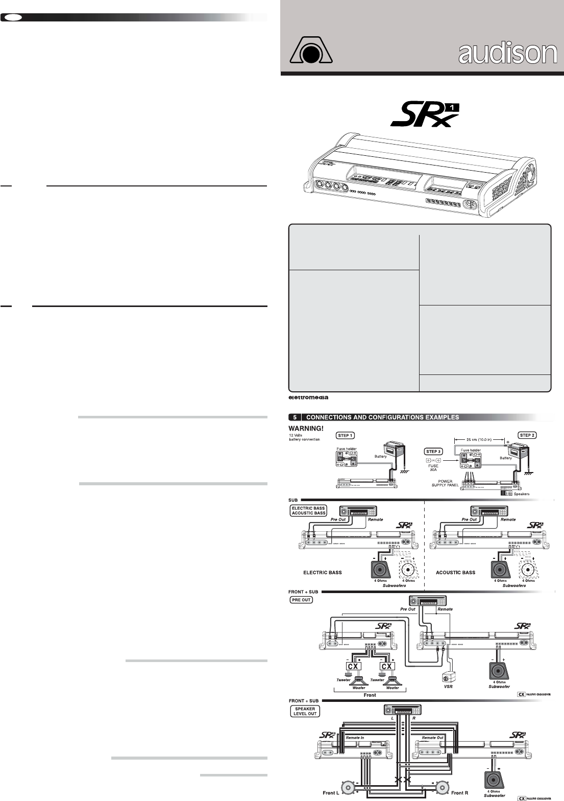
WARNING! For extra protection, we recommend to put a strip
fuse along the cable that connects the battery positive pole to
the amplifier +BATT terminal. This fuse must be installed approx.
25 cm far from the battery. Its value will have to be 50% higher
than the amplifier built-in one. When systems consist of several
amplifiers or of amplifiers with several built-in fuses, the value of
this fuse will have to be 50% higher to the sum of the values of all
other fuses in the system.
5. CONNECTIONS AND CONFIGURATIONS EXAMPLES
1. INSTALLATION
2. CONNECTIONS
3. FUNCTIONS AND CONTROLS
4. CONFIGURATION TABLE
SRx project