STEP 2
Attach the wheel magnet loosely to one
of the spokes on the left side of the front
wheel. Adjust the magnet and sensor
positions by sliding both pieces around
until you get the sensor as high on the
fork blade as possible while still main-
taining the necessary magnet to sensor
spacing (1-2mm). NOTE: The magnet
should pass within 1-2mm of the sensor,
and the top of the magnet should be no
higher than the top of the small arrow
molded into the face of the sensor!
STEP 3
Route the sensor wire up the back of the fork and secure it with electrical tape. Do
not use zip-ties to secure the sensor wire to the fork, as this may result in cut or bro-
ken wires. Be sure to leave enough slack in the wire to allow for the movement of the
handlebar while steering, and the motion of the suspension fork, if your bike is
equipped with one.
STEP 4
Carefully wrap the excess sensor wire around the front brake cable housing, secur-
ing with electrical tape as necessary. When you are finished, you should have just
enough slack for the computer mounting bracket to reach the handlebar. Check to
make sure that all of the excess sensor wire is either taped down or wrapped around
the brake cable so that nothing can snag it during a ride.
BRACKET INSTALLATION
Clamp the bracket around the handlebars and tighten in place. The Ascent 8FC brack-
ets is designed to fit standard 26.0 - 26.4mm diameter road handlebars. Shims are pro-
vided to fit smaller 25.4mm diameter mountain or road bars. Make sure not to over tight-
en the bracket as this may result in breakage. The bracket needs to be tightened only
enough to prevent rotation on the handlebar during normal riding.
HEAD UNIT INSTALLATION
The head unit of the 8FC computer is
designed to lock into the bracket. When
installing the head unit in the bracket, you
should hear an audible “SNAP” indicating
that the unit is locked firmly in place. The
head of the 8FC slides into the bracket
from the front to the back.
TEST OF INSTALLATION
Once you complete the installation proce-
dure, test the unit to make sure that it
works.
STEP 1
Advance the computer to the SPD /
ATM display screen.
STEP 2
Pick up the front of the bicycle and
spin the front wheel. The computer
should register speed within 1-2 sec-
onds. If you do not get a speed read-
ing, check to be sure that the wheel
magnet and sensor are aligned cor-
rectly, and that the space between the
magnet and sensor is 1-2mm or less.
Adjust as necessary and re-test.
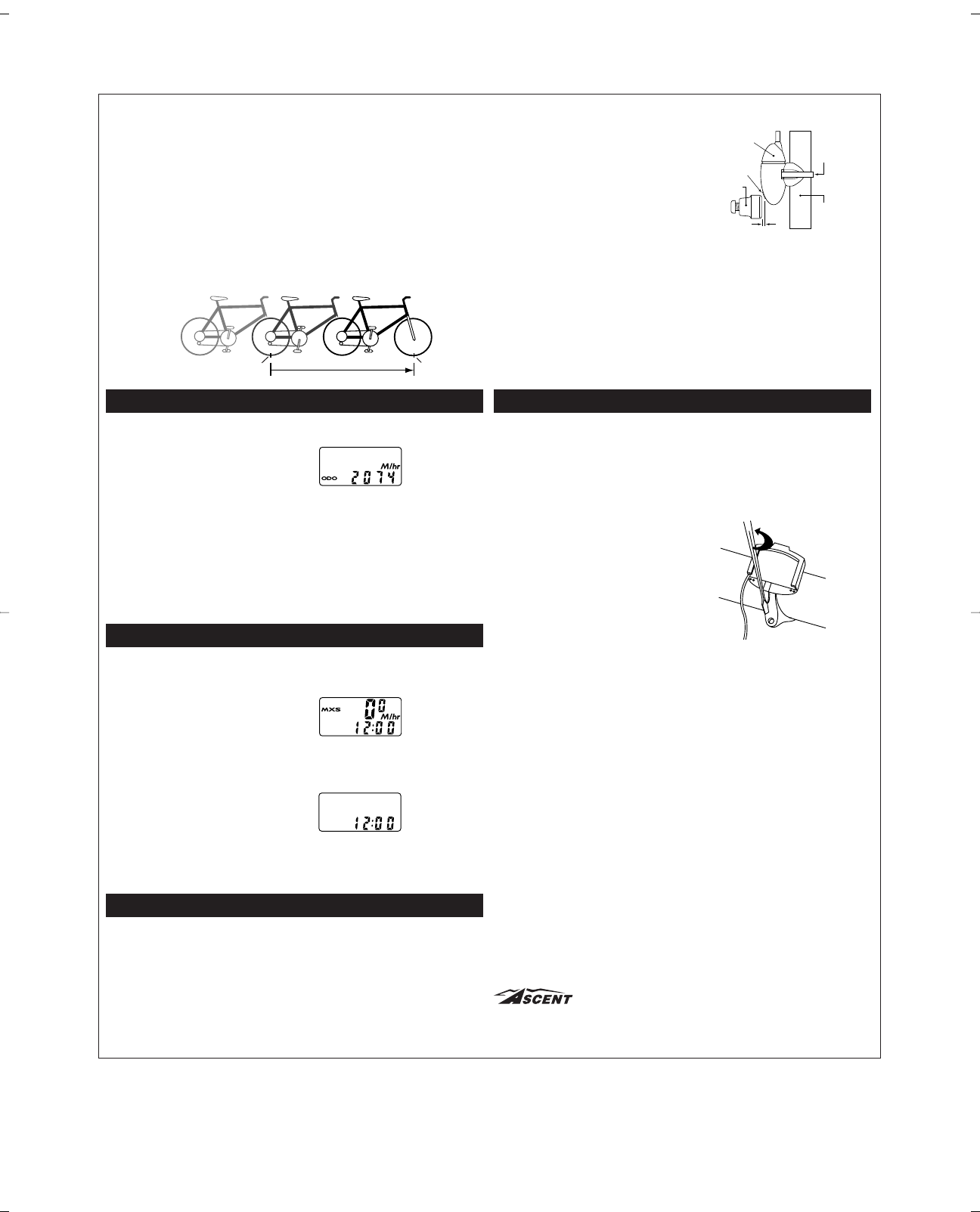
WHEEL SIZE CALCULATION
If your specific tire size is not listed in the chart, follow these steps to measure wheel cir-
cumference.
STEP 1
Stand your bicycle upright. With your tire inflated to its proper pressure, rotate your
front wheel so that the valve is located at the bottom (6 o’clock position). Make a
mark on the floor to indicate the valve location.
STEP 2
Roll the bicycle forward in a straight line for one complete wheel revolution, until the
valve is again at the bottom. Make a mark on the floor to indicate the valve location.
STEP 3
Measure the distance between the marks in millimeters (1 inch = 25.4mm). This
value is your wheel circumference. Enter this value in the computer (see
“Programming Wheel Size” below).
PROGRAMMING WHEEL SIZE
STEP 1
Once you select miles (M/hr) or kilome-
ters (KM/hr) and press the right key (A),
the computer will automatically advance
to the wheel size programming screen.
STEP 2
The factory default setting is 2074 (700 x
20C). The right hand digit (4) will flash.
Use the left key (B) to adjust the value.
STEP 3
Press the right key (A) to set the value and advance to the next flashing digit (7).
STEP 4
Repeat this sequence until all digits have been set to the appropriate value.
STEP 5
Press the right key (A) one final time to enter the wheel size setting into memory,
and return to the AVS / ODO display screen.
SETTING THE CLOCK
The 8FC cycle computer is equipped with a
digital clock that displays time of day in a 12
hour format.
STEP 1
With the computer in the MXS display
screen, press and hold the right key (A)
for 2 seconds.
STEP 2
The screen will clear and the hours will
flash. Advance the hours using the left
key (B). NOTE: Hold this key to quickly
advance the hours. Press the right key
(A) to set the value and advance to the
minutes setting.
STEP 3
Advance the minutes using the left key
(B). NOTE: Hold this key to quickly
advance the minutes. Press the right key
(A) to set the value and return to the
MXS display screen.
MAGNET, SENSOR AND BRACKET INSTALLATION
WHEEL MAGNET, SENSOR AND BRACKET INSTALLATION
We recommend that you install your 8FC in the following manner, starting with the sen-
sor unit on the fork and working up to the mounting bracket on the handlebar.
STEP 1
Mount the sensor loosely (so that you can slide it around) to the fork blade using the
zip-tie provided. The sensor can be mounted at any point along the fork. However,
we recommend a position on the back side and near the top of the left fork blade.
This will protect the sensor from rocks, trees and other objects.
Programming
Wheel Size
Display Showing
Clock Function
Setting the Clock
Function
Distance (in mm)
Valve Valve
Chapel Hill, NC Made in China, V.1 – April 2002
Fork Leg
Zip Tie
Sensor
Alignment
Arrow
Wheel
Magnet
1-2mm