Vorwort
Sehr geehrte Kundin, sehr geehrter
Kunde, wir bedanken uns für den Kauf
dieses Funk-öffnungsmelders. Mit diesem
Gerät haben Sie ein Produkt erworben, das
nach dem heutigen Stand der Technik gebaut
wurde.
Dieses Produkt erfüllt die Anforderungen
der geltenden europäischen und nationalen
Richtlinien. Die Konformität wurde nachge-
wiesen, die entsprechenden Erklärungen und
Unterlagen sind beim Hersteller hinterlegt.
Um diesen Zustand zu erhalten und einen
gefahrlosen Betrieb sicherzustellen, müssen
Sie als Anwender diese Bedienungsanleitung
beachten! Bei Fragen wenden Sie sich an
Ihren Fachhändler. Der Funköffnungsmelder
dient zur Überwachung von Türen und Fens-
tern. Er besteht aus einem Melder und einem
Magneten. Sie werden parallel in einem
geringen Abstand zueinander angebracht.
Ein Alarm wird ausgelöst, sobald sich dieser
Abstand vergrößert (also ein Fenster oder
eine Türe geöffnet werden).
Beachten Sie die Anweisungen und Hinweise
in dieser Anleitung! Sollten Sie sich nicht an
diese Anleitung halten, erlischt Ihr Garan-
tieanspruch! Für Folgeschäden wird keine
Haftung übernommen! Das gesamte Produkt
darf nicht geändert, geöffnet bzw. umgebaut
werden.
Auswahl des Montageortes
Optimaler Montageort für den Funköffnungs-
melder ist die obere Ecke Ihres Fenster-/
Tür-Rahmens. Befestigen Sie den Melder
probeweise mit doppelseitigem Klebeband
und lösen Sie zum Testen einen Alarm aus.
Wurde dieser von der Anlage nicht empfan-
gen, testen Sie den Melder an einer anderen
Stelle. Achten Sie darauf, dass Sie den Mel-
der auf einer ebenen Fläche installieren.
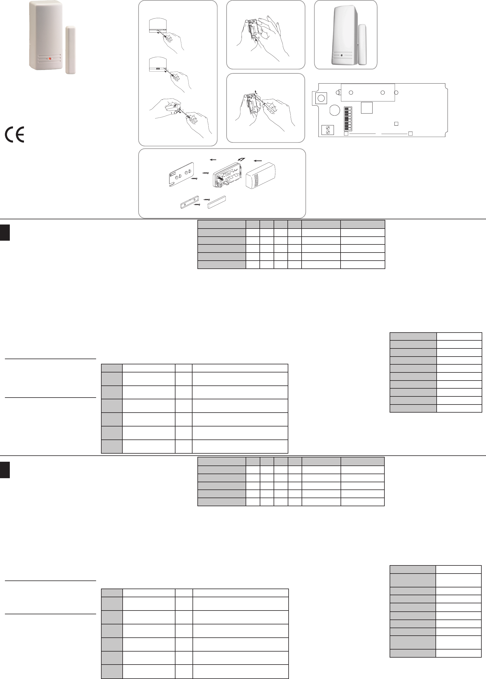
Montage
1. Öffnen Sie das Gehäuse. Nehmen Sie
hierzu einen Schraubendreher und führen
ihn in die Einsparung an der Unterseite
des Melders. Drehen Sie den Schrauben-
dreher vorsichtig, bis sich der Deckel von
der Bodenplatte hebt.
2. Entfernen Sie die Platine. Hebeln Sie sie
dazu vorsichtig aus dem Gehäuse.
3. Montieren Sie den Melder an die ge-
wünschte Stelle. Schrauben Sie hierfür das
Gehäuse des Melders an die Wand.
a. Halten Sie die Gehäuserückseite des
Melders an den Rahmen Ihrer Türe oder
Ihres Fensters.
b. Markieren Sie die Position für die
Schrauben. Nutzen Sie hierfür die zwei
bereits vorhandenen Aussparungen.
c. Befestigen Sie die Gehäuserückwand
an der markierten Stelle.
4. Achten Sie darauf, dass das Gehäuse
ach auf dem Untergrund auiegt, damit
der Wandabrisskontakt geschlossen ist.
5. Drücken Sie die Platine wieder in das Gehäuse.
6. Entfernen Sie die Schutzfolie und legen
Sie die beigefügte Lithium-Batterie polrich-
tig in die vorgesehene Halterung ein.
7. Befestigen Sie den Magneten parallel
neben dem Melder – in einem Abstand von
ca. 10 mm.
8. Verändern Sie je nach Bedarf die Ein-
stellung mit Hilfe der DIP-Schalter und
schließen Sie das Meldergehäuse.
Einlernen
Um den Melder zu nutzen, müssen Sie ihn
an der ABUS Funk-Alarmanlage einlernen.
Gehen Sie dabei wie folgt vor:
1. Setzen Sie Ihre Alarmanlage in den
Einlern-Modus. Der Schriftzug “Warte auf
Signal“ erscheint im Display.
2. Halten Sie den Deckel- und Wandkontakt
des Senders für mindestens drei Sekun-
den gedrückt, um eine Meldung an die
Alarmanlage zu senden.
3. Vergewissern Sie sich an der Alarmanlage,
dass diese den Melder erkannt hat.
4. Setzen Sie Ihre Alarmanlage wieder in den
normalen Betriebsmodus zurück.
Einstellung
Einstellungen des Funköffnungsmelders
werden an der Platine mit acht DIP-Schaltern
(siehe Tabelle) vorgenommen.
LED
Die LED leuchtet bei jedem Sendevorgang.
Bei schwacher Batterie blinkt die LED.
Betriebsmodi
Der Melder sendet eine Alarmmeldung an die
Alarmanlage, wenn ein Alarm ausgelöst wur-
de. Wird der Alarm zurückgesetzt, sendet er
eine Meldung an die Alarmanlage. Innerhalb
von 2,5 Minuten überträgt der Melder nur eine
Alarmmeldung. Sie können eine Meldung zum
Zurücksetzen der Anlage durch erneutes Öff-
nen und Schließen des Kontaktes auslösen.
DIP 1-2 nicht verwendet
DIP 3 Supervision ON:
OFF:
alle 15 Minuten
alle 65 Minuten
DIP 4 Interner Magnetkontakt ON:
OFF:
Ausgeschaltet
Eingeschaltet (Standard)
DIP 5 Magnetkontakt-Typ ON:
OFF:
Normally Closed
Normally Opend (Standard)
DIP 6 Reaktionszeit ON:
OFF:
Langsem, 500 ms
Schnell, 10 ms (Standard)
DIP 7 Alarm-Hold-Funktion ON:
OFF:
2,5 Minuten Ruhezeit
Alarme werden sofort übertragen (Standard)
DIP 8 Sendeleistung ON:
OFF:
niedrig
hoch
Funköffnungsmelder
Radio door contact
Détecteur d’ouverture sans l
Draadloze openingsmelder
Trådløs åbningsdetektor
Anwendung Dip 4 Dip 5 Dip 6 Dip 7 Anschluss (T.B.) Verarbeitungslogik
Magnetkontakt off off on on frei Nur Magnetkontakt
Magnet + extern (NC) off on on on belegt UND (3)
Magnet + extern (NO) off off on on belegt UND (4)
Extern NC on on on on belegt Nur Anschluss
Extern NO on off on on belegt Nur Anschluss
Externe Kontakte anschließen
Sie können externe Melder mit NC- oder NO-
Kontakten an diesen Funk-Öffnungsmelder
anschließen. Bei mehreren Geräten, müssen
diese in Reihe geschaltet sein. Schließen Sie
die externen Geräte an die mit „T.B.“ bezeich-
neten Schraubklemmen auf der Platine an.
Beachten Sie zur Verwendung der externen
Kontakte die Tabelle oben.
Technische Daten
Frequenz 868,65 MHz
HF-Immunität 20V/m 80MHz-1GHz
Modulation AM
Supervision Alle 65 / 15 Minuten
Stromaufnahme ca. 6 μA standby
Batterie CR123 3V Lithium
Batterielebensdauer ca. 5 Jahre
Filter Weißlichtlter
Betriebstemperatur 0°C – 50°C
Abm. (HxBxT) 81 x 35 x 32 mm
(3)Nur wenn sowohl der Magnetkontakt als auch
der extene Kontakt geschlossen sind, ben-
det sich der Öffnungsmelder im Ruhezustand.
Ansonsten wird ein Alarm ausgelöst.
(4)Nur wenn der Magnetkontakt geschlossen
und der extene Kontakt offen ist, bendet
sich der Öffnungsmelder im Ruhezustand.
Ansonsten wird ein Alarm ausgelöst.
Preface
Dear Customer, Thank you for purchasing
this radio door/window contact opening
detector. You made the right decision in
choosing this state-of-the-art technology,
which complies with the current standards
of domestic and European regulations. The
CE has been proven and all related certi-
cations are available from the manufacturer
upon request. To maintain this status and to
guarantee safe operation, it is your obligation
to observe these operating instructions! In the
event of questions, please contact your local
specialist dealer. This radio door/window con-
tact opening detector is used for monitoring
doors and windows. It consists of a detector
and a magnet. These are tted parallel and
close to each other. As soon as the distance
between the two elements increases (i.e., if
the window or door is opened), an alarm is
triggered.
Read carefully the notes and advice in these
operating instructions! If you do not follow
these instructions, your guarantee claim
becomes invalid! We can accept no liability
for the consequences! No part of the product
may be changed or modied in any way.
Selecting the installation location
The best place to install your radio door/win-
dow contact is the upper corner of the win-
dow/door frame. Use double-sided adhesive
tape to x the detector temporarily in different
locations and test it by triggering an alarm. If
it is not detected by the alarm centre, move
the detector to a new position. Make sure you
t the detector to a at surface.
Installation
1. Open the case. Do this by inserting a
screwdriver into the gap at the bottom of
the detector. Turn the screwdriver carefully
until the lid is free of the base.
2. Remove the PC board. Do this by levering
it carefully from the housing.
3. Install the detector at the selected location.
Screw the detector housing to the wall.
a. Hold the housing base against the frame
of the door or window.
b. Mark the positions for the screws. Use
the holes provided for this.
c. Fix the housing base-plate to the mar
-
ked position.
4. Make sure that the housing lies at on the sur-
face so that the wall removal contact is closed.
5. Carefully press the PC board into the casing.
6. Remove the protective foil and insert the
lithium battery provided in the battery clip
(check battery poles!).
7. Fix the magnet parallel to the detector at a
distance of ca. 10 mm.
8. Alter the settings by changing the DIP
switches if necessary, and then close the
detector housing.
Learning
To use the detector, you rst have to train it
on the ABUS radio alarm centre. Proceed as
follows:
1. Switch your alarm centre to learn mode.
You see the message “Scanning for
signal” on the display.
2. Press the lid and wall contact of the transmit-
ter and keep it pressed for at least 3 seconds
to send a message to the alarm centre.
3. Check that the alarm system has recog-
nised the detector.
4. Switch the alarm centre back to normal
operating mode.
Setting
You change the settings of the radio door/
window contact by varying the 8 DIP swit-
ches (see table).
LED
The LED lights up every time a message is
sent. If the battery is low, the LED ashes:
Operating modes
If an alarm is triggered, the detector sends
an alarm message to the alarm centre. If
the alarm is reset, it sends a message to the
alarm centre.
The detector sends only one alarm message
within 2.5 minutes. You can trigger a mes-
sage to reset the alarm centre by opening
and closing the contact again.
Connecting external contacts
You can connect more than one external
detector with NC or NO contacts to this radio
opening detector. Two or more devices must
be serially connected. Connect external de-
vices to the screw clamps marked “T.B.” on
the PC board. See the above table for using
external contacts.
Technical data
Frequency 868.65 MHz
HF immunity 20V/m
80MHz – 1GHz
Modulation AM
Surveillance Every 65 / 15 min.
Power consumption ca. 6 μA standby
Battery CR123 3V Lithium
Battery lifetime ca. 5 years
Filter White-light lter
Ambient operating
temperature
0°C – 50°C
Dimensions (HxWxD) 81 x 35 x 32 mm
DIP 1-2 Not used
DIP3 Supervision
Time setup
ON:
OFF:
every 15 minutes
every 65 minutes
DIP 4 Internal magnet contact ON:
OFF:
Off
On (default)
DIP 5 Magnet contact type ON:
OFF:
Normally Closed
Normally Open (default)
DIP 6 Reaction time ON:
OFF:
Slow, 500 ms
Fast, 10 ms (default)
DIP 7 Alarm-hold function ON:
OFF:
2.5 minutes idle time
Alarms are transmitted immediately (default)
DIP 8 Transmission power ON:
OFF:
low
high
Application Dip 4 Dip 5 Dip 6 Dip 7 Connection (T.B.) Processing logic
Magnetic contact off off on on free Magnetic contact only
Magnet + external (NC) off on on on connected AND (3)
Magnet + external (NO) off off on on connected AND (4)
External NC on on on on connected Connection only
External NO on off on on connected Connection only
3) The door/window contact is in an idle state
only if the magnetic contact and the external
contact are closed. Otherwise, an alarm is
triggered.
(4) The door/window contact is in an idle
state only if the magnetic contact is closed
and the external contact is open. Otherwise,
an alarm is triggered.
DUK