Specifications
Features
Installation
Fuse Replacement
PROTECTOR indicator
Mount the unit as illustrated.
•
(at 4 Ω ).
•This unit can be used as a bridging amplifier
with a maximum output of 250 W.
•Built in Low-pass filter (80 Hz, –18 dB/oct)
and High-pass filter (80 Hz, –12 dB/oct).
•*
1
.
•*
2
for stable and regulated
output power.
•
speaker output of your car audio unit if it is
not equipped with the line output (High level
input connection).
*
1
Protection circuit
This amplifier is provided with a protection circuit
that operates in the following cases:
— when the unit is overheated
— when a DC current is generated
— when the speaker terminals are short circuited.
The PROTECTOR indicator lights up in red, and
the unit will shut down.
If this happens, turn off the connected
equipment, take out the cassette tape or disc, and
determine the cause of the malfunction. If the
amplifier has overheated, wait until the unit cools
down before use.
*
2
Pulse power supply
This unit has a built-in power regulator which
converts the power supplied by the 12 V DC car
battery into high speed pulses using a
semiconductor switch. These pulses are stepped
up by the built-in pulse transformer and
separated into both positive and negative power
supplies before being converted into direct
current again. This is to regulate fluctuating
voltage from the car battery. This light weight
power supply system provides a highly efficient
power supply with a low impedance output.
Indicador PROTECTOR
Before Installation
•
a seat.
•Choose the mounting location carefully so the
unit will not interfere with the normal
movements of the driver and it will not be
exposed to direct sunlight or hot air from the
heater.
•
where the heat dissipation from the unit will
be considerably impaired.
First, place the unit where you plan to install it,
and mark the positions of the four screw holes
on the mounting board (not supplied). Then
drill a 3 mm pilot hole at each mark and mount
the unit onto the board with the supplied
mounting screws. The mounting screws are all
15 mm long, so make sure that the mounting
board is thicker than 15 mm.
Monte la unidad tal como se muestra
en la ilustración.
If the fuse blows, check the power connection
and replace both the fuses. If the fuse blows
again after replacement, there may be an
internal malfunction. In such a case, consult
your nearest Sony dealer.
Warning
When replacing the fuse, be sure to use one
matching the amperage stated above the fuse
holder. Never use a fuse with an amperage
rating exceeding the one supplied with the unit
as this could damage the unit.
Especificaciones
2005 Sony Corporation
2-586-737-11 (1)
Operating instructions
Manual de instrucciones
XM-SD14X
Parts for Installation and Connections
Componentes de instalación y conexiones
12 3
0.2 m
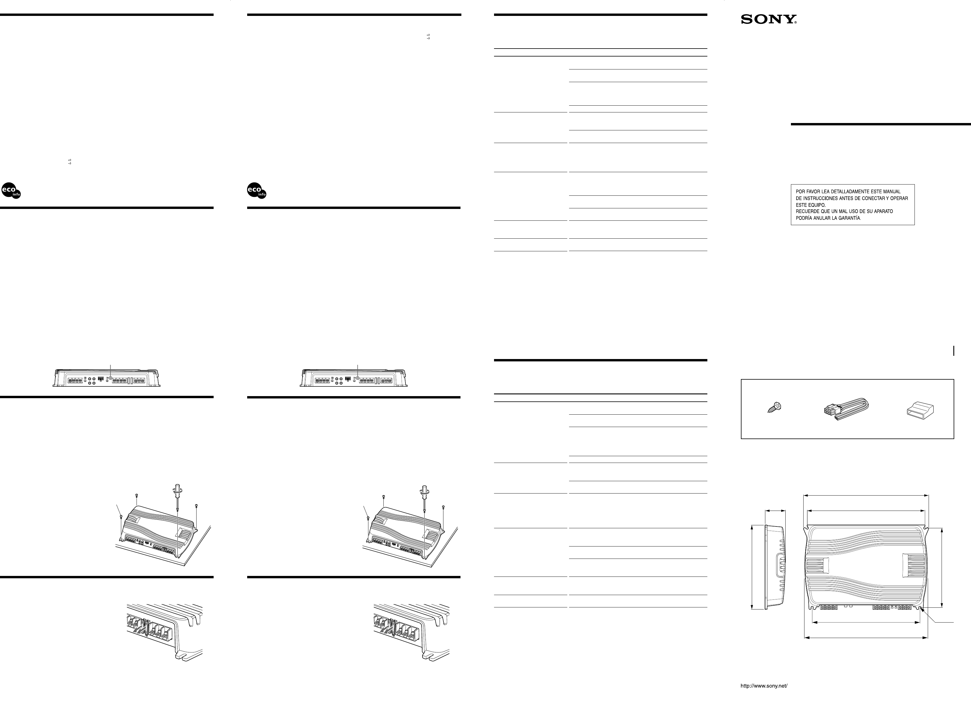
Dimensions
Dimensiones
Unit: mm
Unidad: mm
223
238
ø 6
301
329
55
ø 5 × 15 mm
(× 4)
350
1
1
Ster
Amplifier
Amplificador
Circuit system OTL (output transformerless)
circuit
Pulse power supply
Inputs RCA pin jacks
High level input connector
Input level adjustment range
0.3 – 6 V (RCA pin jacks),
1.2 – 12 V (High level input)
Outputs Speaker terminals
Speaker impedance
2 – 8 Ω (stereo)
4 – 8 Ω (when used as a bridging
amplifier)
Maximum output Four speakers: 100 W × 4 (at 4 Ω)
Three speakers: 100 W × 2 + 250
W × 1 (at 4 Ω )
Rated output (supply voltage at 14.4 V)
55 W RMS × 4 (DIN 45500, 4 Ω)
Four speakers:
50 W RMS × 4 (20 Hz – 20 kHz,
0.04 % THD, at 4 Ω)
60 W RMS × 4 (20 Hz – 20 kHz,
0.1 % THD, at 2 Ω)
SN Ratio 100 dBA (reference: Rated
output)
Frequency response
5 Hz – 50 kHz (
dB)
Harmonic distortion
0.005 % or less (at 1 kHz, 4 Ω , 10
W)
Low-pass filter 80 Hz, – 18 dB/oct
High-pass filter 80 Hz, – 12 dB/oct
Power requirements
12 V DC car battery (negative
ground)
Power supply voltage
10.5 – 16 V
Current drain 30 A (at 4 Ω, 50 W × 4)
Remote input: 1 mA
Dimensions Approx. 350 × 55 × 238 mm (w/
h/d) not incl. projecting parts
and controls
Mass Approx. 3.1 kg not incl.
accessories
Supplied accessories
Mounting screws (4)
High level input cord (1)
Protection cap (1)
Design and specifications are subject to change
without notice.
Sistema de circuito
Circuito OTL (salida sin
transformador)
Fuente de alimentación por
impulsos
Entradas Tomas de pines RCA
Conector de entrada de nivel alto
Margen de ajuste de nivel de entrada
0,3 – 6 V (Tomas de pines RCA)
1,2 – 12 V (Entrada de alto nivel)
Salidas Terminales de altavoz
Impedancia de altavoz
2 – 8 Ω (estéreo)
4 – 8 Ω (cuando se utiliza como
amplificador en puente)
Salida máxima Cuatro altavoces: 100 W × 4 (a 4
Ω)
Tres altavoces: 100 W × 2 + 250
W × 1 (a 4 Ω)
Salida nominal (tensión de suministro a 14,4 V)
55 W RMS × 4 (DIN 45500, 4 Ω)
Cuatro altavoces:
50 W RMS × 4 (20 Hz – 20 kHz,
0,04 % THD, a 4 Ω)
60 W RMS × 4 (20 Hz – 20 kHz,
0,1 % THD, a 2 Ω)
Relación señal-ruido
100 dBA (referencia: Salida
nominal)
Respuesta de frecuencia
5 Hz – 50 kHz ( dB)
Distorsión armónica
0,005 % o inferior (a 1 kHz, 4 Ω , a
10 W)
Filtro de paso bajo 80 Hz, – 18 dB/oct
Filtro de paso alto 80 Hz, – 12 dB/oct
Requisitos de alimentación
Batería de automóvil de cc de 12
V (negativo a masa)
Tensión de fuente de alimentación
10,5 – 16 V
Consumo de energía
30 A (a 4 Ω , 50 W × 4)
Entrada remota: 1 mA
Dimensiones Aprox. 350 × 55 × 238 mm (an/
al/prf), componentes y controles
salientes excluidos
Peso Aprox. 3,1 kg, accesorios
excluidos
Accesorios suministrados
Tornillos de montaje (4)
Cable de entrada de alto nivel (1)
Cubierta protectora (1)
Diseño y especificaciones sujetos a cambios sin
previo aviso.
343
Sustitución del fusible
Si el fusible se funde, compruebe la conexión de
alimentación y sustituya ambos fusibles. Si el
fusible se funde de nuevo después de
sustituirlo, es posible que exista un fallo de
funcionamiento interno. En este caso, póngase
en contacto con el distribuidor Sony más
próximo.
Advertencia
Al sustituir el fusible, asegúrese de utilizar uno
cuyo amperaje coincida con el especificado en
el portafusibles. No utilice nunca un fusible con
un amperaje superior al del suministrado con la
unidad, ya que podría dañarla.
Instalación
Antes de realizar la instalación
•Monte la unidad en el interior del maletero o
debajo de un asiento.
•Elija cuidadosamente el lugar de instalación
de forma que la unidad no dificulte los
movimientos normales del conductor y no
quede expuesta a la luz solar directa ni al aire
caliente de la calefacción.
•
suelo, en cuyo caso la disipación de calor de la
misma disminuirá considerablemente.
En primer lugar, coloque la unidad donde
tenga previsto instalarla y marque sobre la
superficie del tablero de montaje (no
suministrado) las posiciones de los cuatro
orificios para los tornillos. A continuación,
perfore los orificios con un diámetro de
aproximadamente 3 mm y monte la unidad
sobre el tablero con los tornillos de montaje
suministrados. Ya que la longitud de estos
tornillos es de 15 mm, compruebe que el grosor
del tablero de montaje sea superior a 15 mm.
Características
•Salida máxima de potencia de 100 W por canal
(a 4 Ω ).
•
amplificador en puente con una salida máxima
de 250 W.
•Filtro de paso bajo (80 Hz, –18 dB/oct) y filtro
de paso alto (80 Hz, –12 dB/oct) incorporados.
•Circuito de protección*
1
incorporado.
•*
2
para
obtener una potencia de salida estable y
regulada.
•
salida de altavoz del sistema de audio para
automóvil si éste no está equipado con salida
de línea (conexión de entrada de alto nivel).
*
1
Circuito de protección
Este amplificador dispone de un circuito de
protección que se activa en los siguientes casos:
— Si la unidad se calienta excesivamente
— Si se genera corriente cc
— Si se produce un cortocircuito en los terminales
del altavoz.
El indicador PROTECTOR se iluminará en rojo y la
unidad se desactivará.
Si esto ocurre, desactive el equipo conectado,
extraiga la cinta de casete o el disco y determine
la causa del fallo de funcionamiento. Si el
amplificador se ha sobrecalentado, espere hasta
que la unidad se enfríe antes de volver a utilizarla.
*
2
Fuente de alimentación por impulsos
Esta unidad dispone de un regulador de potencia
incorporado que convierte la fuente de
alimentación de cc de 12 V de la batería del
automóvil en impulsos de alta velocidad mediante
un interruptor semiconductor. Estos impulsos se
incrementan mediante el transformador de
impulsos incorporado y se dividen en fuente de
alimentación positiva y negativa antes de volver a
convertirse en corriente directa. Este sistema de
fuente de alimentación de peso ligero
proporciona una alta eficacia del suministro con
una salida de baja impedancia.
•Packaging cushions do not use polystyrene foam.
•
•Halogenated flame retardants are not used in the cabinets.
•Halogenated flame retardants are not used in the certain printed wiring boards.
•No se ha utilizado goma esponjosa de poliestireno para el material de relleno y protección.
• Se ha utilizado soldadura sin plomo para ciertas partes.
• Los chasis impresos no contienen retardantes de llama halogenados.
• Ciertas placas del circuito impreso no contienen retardantes de llama halogenados.
Troubleshooting Guide
The following checklist will assist in the correction of most problems which you may encounter with
your unit.
Before going through the checklist below, refer to the connection and operating procedures.
Problem
Blue illumination does not light
up.
The PROTECTOR indicator Lights
up in red.
• The unit becomes abnormally
hot.
• The sound is interrupted.
Alternator noise is heard.
The sound is muffled.
The sound is too low.
Cause/Solution
The fuse is blown.
t Replace both the fuses with a new one.
The ground wire is not securely connected.
t Fasten the ground wire securely to a metal point of the car.
The voltage going into the remote terminal is too low.
•
t Turn on the car audio unit.
• The system employs too many amplifiers. t Use a relay.
Check the battery voltage (10.5 – 16 V).
Turn off the power switch. The speaker outputs are short-
circuited.
t Rectify the cause of the short circuit.
Turn off the power switch. Make sure the speaker cord and
ground wire are securely connected.
The unit heats up abnormally.
•
t 2 – 8 Ω (stereo) , 4 – 8 Ω (when used as a bridging amplifier).
• Make sure to place the unit in a well ventilated location.
The thermal protector is activated. t Reduce the volume.
The power connecting wires are installed too close to the RCA pin
cords.
t Keep the power connecting wires away from the RCA pin
cords.
The ground wire is not securely connected.
t Fasten the ground wire securely to a metal point of the car.
Negative speaker cords are touching the car chassis.
t Keep the cords away from the car chassis.
The FILTER selector switch (LPF) is set to the “ON” position.
t When connecting the full range speaker, set to the “OFF”
position.
The LEVEL adjustment control is not appropriate. Turn the
LEVEL adjustment control in the clockwise direction.
Guía de solución de problemas
La siguiente lista le resultará útil para solucionar la mayoría de los problemas que puedan surgir con
la unidad.
Antes de consultar la lista, examine los procedimientos de conexión y funcionamiento.
Problema
La luz azul no se enciende.
El indicador PROTECTOR está
encendido en rojo.
• La unidad se calienta de forma
exagerada.
• El sonido se interrumpe.
Se oye ruido del alternador.
El sonido se amortigua.
El sonido es demasiado bajo.
Causa/Solución
El fusible se ha fundido.
t Sustituya ambos fusibles por unos nuevos.
El cable de toma a tierra no se ha conectado de forma segura.
t Fíjelo firmemente a un punto metálico del coche.
El voltaje que se envía al terminal remoto es demasiado bajo.
•El sistema de audio para automóvil conectado está apagado.
t Encienda el sistema de audio para automóvil.
•El sistema emplea demasiados amplificadores.
t Utilice un relé.
Compruebe la tensión de la batería (10,5 – 16 V).
Apague el interruptor de alimentación. Se ha producido un
cortocircuito en las salidas de altavoz.
t Rectifique la causa del cortocircuito.
Apague el interruptor de alimentación. Asegúrese de que el cable
del altavoz y el de toma a tierra estén conectados firmemente.
La unidad se calienta de forma exagerada.
•Utilice altavoces con una impedancia adecuada.
t 2 – 8 Ω (estéreo) , 4 – 8 Ω (cuando se utiliza como
amplificador en puente).
•Coloque la unidad en un lugar bien ventilado.
Se ha activado el protector térmico. t Reduzca el volumen.
Los cables de conexión de alimentación se encuentran demasiado
cerca de los cables de pines RCA.
t Manténgalos alejados entre sí.
El cable de toma a tierra no se ha conectado de forma segura.
t Fíjelo firmemente a un punto metálico del coche.
Los cables negativos del altavoz están en contacto con el chasis del
automóvil.
t Manténgalos alejados del chasis.
El selector FILTER (LPF) está ajustado en la posición “ON”.
t Al conectar el altavoz de rango completo, ajuste el selector en
la posición “OFF”.
El control de ajuste LEVEL no es apropiado. Gire el control de
ajuste LEVEL en el sentido de las agujas del reloj.