This device is designed to detect the presence of fire inside residential or commercial
buildings. It should not be installed in industrial premises.
The detector has a built-in local warning siren combined with a red LED indicator. It
is powered by Type A or B external uninterruptible power sources in
conformity with EN 50131-6, or a security alarm system control panel.
The alarm signal output for these control panels is provided by an electronic
relay via the OUT terminals. A signal concerning detector removal from the
holder is available via the TMP terminals.
The SD-280 detector combines an optical smoke sensor with a heat sensor. Both
sensors have their outgoing signals processed digitally, resulting in higher false
alarm immunity. The optical sensor works using a light diffusion principle and is very
sensitive to the presence of large-sized particles which are characteristic of dense
smokes. By contrast, the sensor is less sensitive to small-sized particles which are
typical of cleanly burning fires. In particular, the smoke sensor is not capable of
detecting the by-products of cleanly-burning fluids such as alcohols, for instance.
This deficiency is compensated for by the built-in heat sensor. This sensor provides
a slower reaction when compared to the smoke sensor, but is much better at
reacting to fires with rapidly rising heat producing only a little smoke.
Detection range, detector positioning
Exposing fire conditions to the smoke and heat sensors requires some level of air
circulation. It is therefore necessary to install the detector in such a place on the
ceiling that (in the case of fire) smoke masses are forced to go in the direction of the
detector’s position. This can usually be achieved in most buildings. However, the
detector is not suitable for installation in outdoor spaces or interiors with an extremely
high ceiling where fire by-products would not reach the detector position.
The following table shows the detector’s working range in relation to the height of
the ceiling on which the detector is installed. The range is expressed as the radius of
the circular fire detection area for a detector installed on a ceiling directly above:
Ceiling height (m)
< 4,5
4,5÷6 6÷8 8÷11 11÷25
> 25
Smoke
detection
7,5* m 7,5* m 7,5* m 7,5* m
Not suitable
Not
applicable
Heat
detection
5* m 5* m 5* m
Not suitable
Not
applicable
Not
applicable
Not applicable – meant for a particular ceiling height range
Not suitable –not usually used in such cases
* – the radius of the detection area below the detector
•Installation on a horizontal level ceiling
Due to the possible occurrence of a cold air layer right under the ceiling, the
detectors must not be imbedded into the ceiling. The distance between any
point to be protected and an imaginary vertical line from the nearest SD-280
detector down to the floor must not exceed the radius indicated in the table.
•Installation on a sloping ceiling
If the SD-280 is installed just under an apex formed by the joining of two
sloping ceilings the values indicated in the table can be increased by 1% for
every degree of slope up to a maximum of 25%. If the space to be protected
is under a saw-tooth type of roof, SD-280 detectors should be installed
under each apex. However, a roof with a shallow saw-tooth form can be
acceptable if the height difference between the highest and lowest parts of
the ceiling does not exceed 5% of the total ceiling height
•Walls, partitions, obstacles, and trussed ceilings
The SD-280 must not be installed closer than 0.5 m from any wall or
partition. A narrow room with a width of less than 1.2m requires the
detector(s) to be placed at a distance of at least one third of the room’s width
away. In the case of separating walls (partitions, warehouse objects) which
do not reach the ceiling, the space is considered to be fully separated if
the gap between the top of the separating wall and the ceiling does not
exceed 0.3 m. A free space of at least 0.5m is required under the detector.
Irregularities in ceiling shape which do not exceed 5% of ceiling height are
considered insignificant – the ceiling can be regarded as being even and
limits from the table are applicable. However, any irregularity (including
beams) exceeding 5% of the ceiling height is considered to be a wall
with the consequences stated above.
•Ventilation and air circulation
The detectors must not be installed directly by a fresh air inlet, e.g. air
conditioning vents. In the case of air being supplied through a perforated ceiling, each
detector must be placed so that no perforation hole occurs within 0.6m of the detector.
•Avoid installing the detector in the following locations:
•Places with poor air circulation (niches, corners, apexes of A-shaped roofs).
•Places exposed to dust, cigarette smoke or steam.
•Places with over-intense air circulation (close to ventilators, heat sources or air
conditioning outlets).
•Kitchens and other cooking places (because steam, smoke or oily fumes can
reduce detector sensitivity).
Caution: The most common reason for the detector to be
accidentally triggered is improper detector location.
See CEN/TS 54-14 standards for detailed installation guidelines.
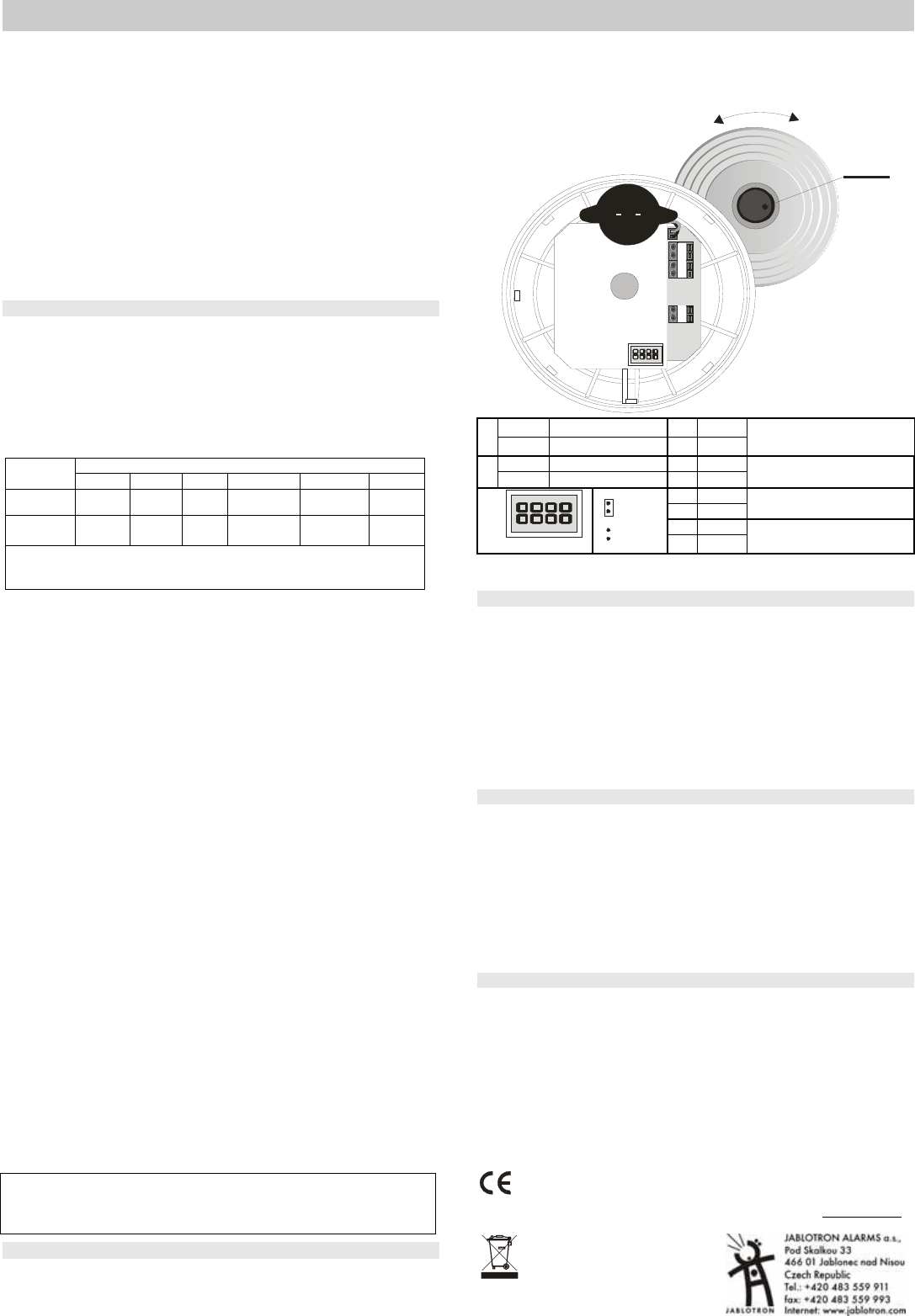
Installation
1. Open the detector by turning the rear cover to the left
2. Screw the rear cover onto the desired location
3. connect the OUT and TMP terminals – consult the control panel manual
before connecting wires to the detector terminal board
4. Set the required function via the jumpers– see the table below
5. Connect the power supply to the 12V terminals – regardless of polarity
6. After installing the detector, allow approx. 20 seconds for stabilisation. This
period is indicated by the LED being continuously lit and is followed by an auto-
test. Successful performance of the auto-test is confirmed acoustically
TEST
1
TMP A LARM
+ 12V -
O
p
e
n
C
l
o
s
e
ON
NO closing contact
3 OFF
1
OFF
NC break contact
4 OFF
Smoke (EN 14064) or heat
(EN 54-5)
ON
Memory ON
3 ON
2
OFF
Memory OFF
4 OFF
Only smoke (EN 14604) (heat
indifferent)
3 OFF
4 ON
Only heat (EN 54-5) (smoke
indifferent)
3 ON
1
1234
ON
OFF
4 ON
Smoke and heat (both
simultaneously)
Testing the detector is automatically performed up to 10 secs after
battery insertion. New settings are saved directly afterwards.
Fire alarm
Optical smoke sensor: Smoke entry into the detector is indicated as a pre-alarm
state by the LED flashing. If the smoke threshold density is exceeded, a siren sound
is generated, gradually increasing in volume.
Heat sensor: indication logic is equal to that of the smoke sensor.
Alarm memory: It is switched ON/OFF via DIP 2 as shown in the table. If the event
memory is armed at the time of alarm, alarm LED indication continues even if normal
conditions are restored. The indication can be stopped by pressing the button.
Silencing the siren during an alarm: During a fire alarm, the detector LED flashes 2
times briefly and the built-in siren sounds (at a higher intensity than during a test). Under
these conditions the siren can be silenced by pressing the test button for approx. 3sec.
However, if normal conditions are not restored within approx. 10 minutes (the smoke
does not clear from the room or the temperature does not drop), the siren re-activates.
Testing the detector
Testing the detector is automatically performed up to 10 secs after
battery insertion or after changing the settings on the jumpers.The
functioning of the detector can be tested by pressing and holding the test button for
approx. 3 seconds. A properly functioning detector responds with one beep and a
short flash. The output is concurrently switched ON / OFF (see the table)
A fault is indicated by 4 beeps and the LED permanently flashing. In this case,
remove the battery and re-insert it after 1 minute. If the fault indication occurs again (the
LED starts permanently flashing after about 1 minute), consult the installer company.
The detector should be tested this way at least once in every 30 days.
Warning: Never start a fire in a building to test the detector. Instead, use smoke-
simulating aerosols for realistic testing.
Specification
Voltage 9 – 15 V DC / 2,5 mA (100mA during alarm)
(Type A or B source pursuant to EN 50131-6)
Outputs - alarm - OUT 60 V/ 100 mA max.
- sabotage (failure) TMP R = 68 Ω (protection)
Smoke detection optical, light dispersion
Smoke sensor sensitivity m = 0.11 - 0.13 dB/m pursuant to EN 14 604
Temperature detection A2 class pursuant to EN 54-5
Fire-alarm temperature +60 °C to + 70 °C
Acoustic power of the built-in siren min. 85dB / 3 m
Operational temperature range -10 to +70 °C
Dimensions diameter 126 mm, height 65 mm
Complies with EN 14 604, A2 EN 54-5, EN 50130-4, EN 55022
1293-CPD-0095
JABLOTRON ALARMS a.s. hereby declares that the SD-280 is in
compliance with the essential requirements and other relevant
provisions of Directive 1999/5/EC. The original of the conformity
assessment can be found on the web site www.jablotron.com
,
Technical Support section
Note: Dispose of batteries safely depending
on battery type and local regulations.
Although this product does not contain any
harmful materials we suggest you return the
product to the dealer or directly to the
manufacturer after use.
Hulp nodig? Stel uw vraag in het forum
Misbruik melden
Gebruikershandleiding.com neemt misbruik van zijn services uitermate serieus. U kunt hieronder aangeven waarom deze vraag ongepast is. Wij controleren de vraag en zonodig wordt deze verwijderd.
Product:
Spelregels forum
Om tot zinvolle vragen te komen hanteren wij de volgende spelregels:
lees eerst de handleiding door;
controleer of uw vraag al eerder door iemand anders is gesteld;
probeer uw vraag zo duidelijk mogelijk te stellen;
heeft u een probleem en al geprobeerd om dit op te lossen, vermeld dit erbij aub;
heeft u een oplossing gekregen van een bezoeker dan horen wij dat graag in dit forum;
wilt u een reactie geven op een vraag of antwoord, gebruik dan niet dit formulier maar klik op de knop 'reageer op deze vraag';
uw vraag wordt direct op de website gezet; vermijd daarom persoonlijke gegevens in te vullen;
Belangrijk! Als er een antwoord wordt gegeven op uw vraag, dan is het voor de gever van het antwoord nuttig om te weten als u er wel (of niet) mee geholpen bent! Wij vragen u dus ook te reageren op een antwoord.
Belangrijk! Antwoorden worden ook per e-mail naar abonnees gestuurd. Laat uw emailadres achter op deze site, zodat u op de hoogte blijft. U krijgt dan ook andere vragen en antwoorden te zien.
Abonneren
Abonneer u voor het ontvangen van emails voor uw Jablotron SD-280 bij:
nieuwe vragen en antwoorden
nieuwe handleidingen
U ontvangt een email met instructies om u voor één of beide opties in te schrijven.
Ontvang uw handleiding per email
Vul uw emailadres in en ontvang de handleiding van Jablotron SD-280 in de taal/talen: Engels als bijlage per email.
De handleiding is 1,48 mb groot.
U ontvangt de handleiding per email binnen enkele minuten. Als u geen email heeft ontvangen, dan heeft u waarschijnlijk een verkeerd emailadres ingevuld of is uw mailbox te vol. Daarnaast kan het zijn dat uw internetprovider een maximum heeft aan de grootte per email. Omdat hier een handleiding wordt meegestuurd, kan het voorkomen dat de email groter is dan toegestaan bij uw provider.
Uw handleiding is per email verstuurd. Controleer uw email
Als u niet binnen een kwartier uw email met handleiding ontvangen heeft, kan het zijn dat u een verkeerd emailadres heeft ingevuld of dat uw emailprovider een maximum grootte per email heeft ingesteld die kleiner is dan de grootte van de handleiding.
Er is een email naar u verstuurd om uw inschrijving definitief te maken.
Controleer uw email en volg de aanwijzingen op om uw inschrijving definitief te maken
U heeft geen emailadres opgegeven
Als u de handleiding per email wilt ontvangen, vul dan een geldig emailadres in.
Uw vraag is op deze pagina toegevoegd
Wilt u een email ontvangen bij een antwoord en/of nieuwe vragen? Vul dan hier uw emailadres in.