Plug
Maximum pipe length
RAC-08LH1 : 10m
RAC-10LH1 : 10m
RAC-14LH1 : 15m
4
5
3
6
1
2
Be sure to
completely
seal any gap.
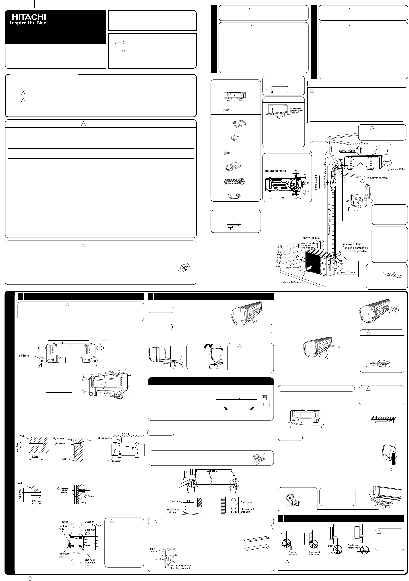
● The difference in height
between the indoor and
outdoor unit should be
kept max 10m.
●
no matter big or small,
should all be insulated
with insulation pipe and
then wrapped with vinyl
tape. (The insulator will
deteriorate if it is not
wrapped with tape).
The connection of insulated
drain hose.
Please use insulated drain
hose for the indoor piping
(commercial product).
The indoor piping should be
insulated with the enclosed
insulation pipe. (If the
insulator is insufficient,
please use commercial
products).
inner diameter 1 mm
SPLIT UNIT AIR CONDITIONER
INST
Indoor Unit Outdoor Unit
RAS-08LH1/RAS-08LH1(B) RAC-08LH1
RAS-10LH1/RAS-10LH1(B) RAC-10LH1
RAS-14LH1/RAS-14LH1(B) RAC-14LH1
●
installation before starting installation work.
●
the correct operation of installation.
SAFETY PRECAUTION
!
!
!
!
● Axists.
A
● Do not install the unit near a location where there is Á
catch À
● Please ensure smooth Á
● Piping shall be suitable supported with a max imum spacing of 1m between the supports.
● Please request your sales agent or qualiÀ
you do the installation work yourself.
● Please observe the instructions stated in the installation manual during the process of installation. Improper installation may
cause water leakage, electric shock and À
● Make sure that the units are mounted at locations which are able to provide full support to the weight of the units. If not,
the units may collapse and impose danger
● Observe the rules and regulations of the electrical installation and the methods described in the installation manual when
dealing with the electrical work. Use power cables approved by the authorities of your country
● Be sure to use the speciÀ
after the conductors of the wire are inserted into the terminals. Improper insertion and loose contact may cause over-heating
and À
● Please use the speciÀ
and À
● Be sure to use the speciÀ
● When installing or removing an air conditioner
pressure in the refrigeration cycle may become abnormally high so that a rupture may be caused.
● Be sure to ventilate fully if a refrigerant gas leak while at work. If the refrigerant gas comes into contact with Àsonous
gas may occur
● After completion of installation work, check to make sure that there is no refrigeration gas leakage. If the refrigerant gas
leaks into the room, coming into contact with À
● Unauthorized modiÀ
conditioner technician or electrician. Improper repairs may result in water leakage, electric shock and À
FOR SERVICE PERSONNEL
THE CHOICE OF MOUNTING SITE (Please note the following matters and obtain permission from customer before installation).
!
●
which can provide full support to the unit.
!
●
port heavy weight. Otherwise, noise and vibration will increase.
!
●
No nearby heat source and no obstruction near the air outlet is allowed.
●
The clearance distances from top, right and left are speciÀ
below
●
The location must be convenient for water drainage and pipe connection
with the Outdoor unit.
●
controller at least 1m from the radio, television and inverter type
Á lamp.
●
T
please put the controller far away from high-frequency machines and
high-power wireless systems.
●
!
●
xpose the unit under direct sunshine or rain. Besides, ventilation
must be good and clear of obstruction.
●
The air blown out of the unit should not point directly to animals or plants.
●
The clearances of the unit from top, left, right and front are speciÀ
À
●
Be sure that the hot air blown out of the unit and noise do not disturb the
neighbourhood.
●
smoke.
●
The location must be convenient for water drainage.
●
Place the Outdoor unit and its connecting cord at least 1m away from the
antenna or signal line of television, radio or telephone. This is to avoid noise
interference.
●
Do not install outdoor unit facing strong wind direction. It may damage the
fan motor
INDOOR UNIT
Names of Indoor Components
Hanger
Qty Item
The Length of Indoor Unit Con-
necting Cord
Figure showing the Installation of Indoor and Outdoor Unit.
OUTDOOR UNIT
1
1
Screw for holder of
Remote Controller
(3.1x 16)
AAA
Direction of Piping
Holder for Remote
Controller
There are 4 directions
allowed, namely
perpendicular to the unit,
vertically down from right,
horizontally out from right and
horizontally out to left.
Don’t form the piping downward
at the left of the unit.
(4.1x 32)
Remote Controller
Purifying Filter
2
6
3
1
4
2
5
2
6
7
9
2
1
Screw for Hanger
Names of Outdoor Components
Qty Item
Drain Pipe
1
Connection
!
CAUTION
•
The installation height of indoor
unit must be 2.3m or more.
8
Holder
1
Installation of Hanger
1
!
● The draining of the water container inside the indoor unit can be done from the
left. Therefore the hanger must be Àxed horizontally or slightly tilted towards the
side of drain hose. Otherwise, condensed water may overÁ
Direct Mounting On The W
● Please use hidden beams in the wall to hold the hanger
W
●
wall which is slightly tilted
towards the outdoor side.
Drill the wall at a small
angle.
●
according to the wall
thickness.
●
of protection pipe should
be completely sealed with
putty to avoid dripping of
rain water into the room.
Installation of the Indoor Unit
2
VERTICALL
Please pull the lower part of
the Indoor unit outwards to
check if the unit is hooked
onto the hanger
installation may cause
vibration and noise.
!
CAUTION
HORIZONT
Preparation
Change of Drain Hose and Installation Procedures.
●
Ex change the location of drain hose and drain cap during horizontal piping as shown in
À
● Please use pliers to pull out the drain cap.
(This is an easier way to remove the drain cap).
INST
● The refrigerating pipes should be adjusted to À t into the
hole on the wall and then ready for further connection.
● The terminals of 2 connected pipes must be covered
with insulator used for terminal connection. Then the
pipes are wrapped with insulation pipe.
●
cover
●
into the space available under the indoor unit. Use
holder to hold them tight.
!
CAUTION
●
The rubber strap used for
À xing the insulator should
not be tied with great force.
Otherwise, this will damage
heat insulation and causes
water condensation.
● Holder can be attached at the either of 2 places.
Please select the easier position.
THE CONNECTION OF REFRIGERA
INST
Preparation T
!
CAUTION
● Please x in the plastic core
after Á
chips entering the pipes.
CAUTION
!
Y
hose. Please ensure the smooth Á
unit during installation. (Carelessness may result in water leakage.)
!
CAUTION
Be sure that the
drain hose is not
loosely connected
or bend.
Be sure that the wire is not
in contact with any metal
in the wall. Please use
the protection pipe as wire
passing through the hollow
part of the wall so as to
prevent the possibility of
damaged by mouse.
Unless it seals completely
any air with high humidity
flows from outdoor and
any dew may drop.
!
W
●
transform and are attached.
● The end of the refrigerating pipes are at locations
marked with “
” symbol.
Installation of Drain Hose
3
Installation
Hang the Indoor unit onto the hanger
stand at the back of the Indoor unit to push its lower part
15cm forwards.
● Place the drain hose through the hole on the wall.
●
connecting refrigerating pipe.
●
(Refer to “Connection of Power Cord”)
● After adjustment, the connecting cord and refrigerating pipes
are placed into the space available under the Indoor unit.
● The projection of Indoor unit must hook to the hanger
INDOOR UNIT
<
IA765: A
>
HOW TO REMOVE INDOOR UNIT
●
bottom of the indoor unit and pull the
bottom plate towards you. Then the
claws are released from the stationary
plate.
(The (PUSH) sections are indicated by
2 arrows in the right À
Connecting cords, pipe and
drain hose must be laid
together with inyl tape.
!
CAUTION
Condensed water may leak out if not inserted properly
HORIZONT
●
openings as shown in À
openings with a À le.
●
portion of pipe-support by hand.
Pipe
Connecting
cord
Drain hose
Insulation pipe (must be wrapped with
vinyl tape at every 120mm).
Holder
Pipe
Rubber strap tied with great force
below
5mm
Please bend at a small
radius to form an arc
0. 5m
Protection pipe
Connecting cord
Holder
Connected section
Drain hose
Heat insulation pipe
Connecting
cord
Refrigerating pipe
Pull this to the front
during the connection
of refrigerating pipes
to ease task.
125mm
45mm
200mm
60mm
0mm
0mm
125mm
2 0mm
45mm
115mm
450mm
Lev
Hanger
Hole for pipe
Weight
Mark
Line
Please use more
than 4 screws.
Screw for Hanger
Lift the body
of the unit
upwards and
then force it
downwards.
Hanger
Refrigerating
Pipe
Protection
Pipe
Drain Hose
Connecting
Cord
Hanger
1
Projection
2
CAUTION
Dimension of Mounting Stand
of the Outdoor unit
(unit : mm)
CAUTION
Preparation
● Connect connecting cord.
● Pull out the pipe, connecting cord and drain hose.
Installation
● The upper part of the Indoor unit is hanged on the hanger
● The projection at the lower part of the Indoor unit is hooked onto the hanger.
W W
CAUTION
CAUTION
W
● Read the safety precautions carefully before operating the unit.
● The contents of this section are vital to ensure safety
W
CAUTION ......... Improper installation may result in serious consequence.
Be sure that the unit operates in proper condition after installation. Ex plain to customer the proper way of
operating the unit as described in the user’s guide.
Procedures of Installation and Precautions
● Procedures to Àx the hanger
1. 2. 3. Fix the hanger on wall
(As shown below) (As shown below) with 4.1 x 32 screw
(As shown in À
● Procedures to Àx the holder of remote control.
1. 2.
(As shown below) (As shown below)
●
+
– Screwdriver
● Measuring T
● Knife
● Saw ● ø 65mm Power Drill ● Hex agonal Wrench
Key ( 4mm)
● Wrench (14, 17, 22mm)
● Gas
Leakage Detector
● Pipe Cutter ● Putty
● Vinyl
T ● Pliers ● Flare T● V
● File
● Manifold V● Charge Hose ● Reamer
TOOLS NEEDED FOR INST
!
In case the pipe length is more than the recommended length
for chargeless, add r
the maximum pipe length.
CAUTION
Model Max . Pipe Chargeless up to Additional R410A
RAC-08LH1
RAC-10LH1
RAC-14LH1
5gram / meter
5gram / meter
20gram / meter
10m
10m
15m
5m
5m
8m
(EN1) INS RAS/RAC-8/10/14LH1 1 3/31/11 9:15 AM